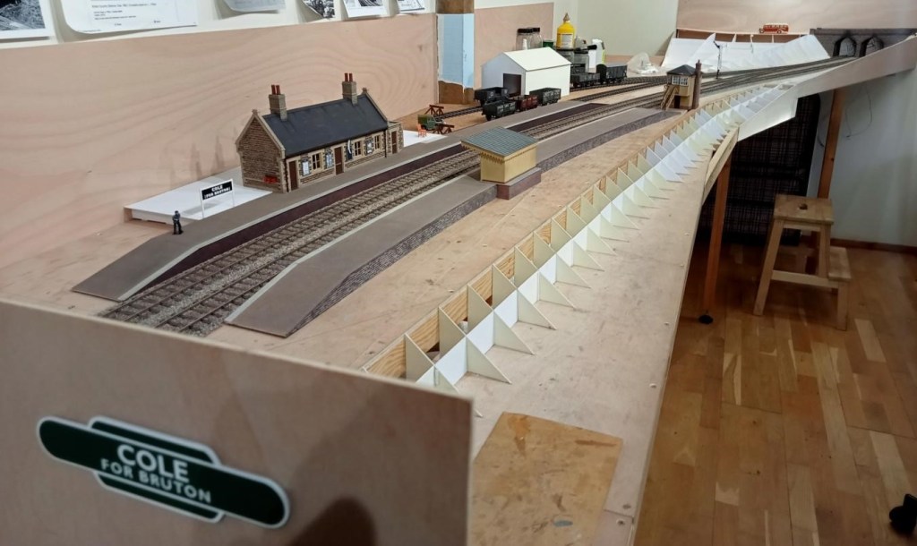
Allan is making good progress on his 7mm rendition of Cole. Platforms have been started and landscape formwork started. The platform surface was finished using fairly fine emery paper dusted with weathering powders (and brushed off outside as the stuff gets everywhere!).
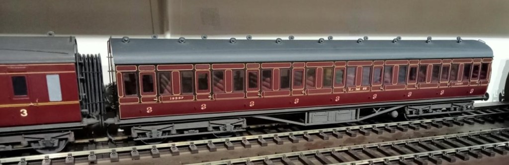
This is a recently acquired LMS Period 1 all third coach built and painted by the Sidelines man himself Malcolm Binns. Jim couldn’t resist it even though outside his period as the lining is outstanding. Unfortunately Jim had to refix the seating and entirely reglaze it – old model, old glue!

Andrew has been busy planning and ordering parts for his O gauge layout Crucaern Station (Anglo Saxon for Crewkerne. “Cruc” is hill and “aern” is a place or building). He’s taken delivery of a large box of points and track from DCC Train Automation.
Below a few words to describe what should happen.
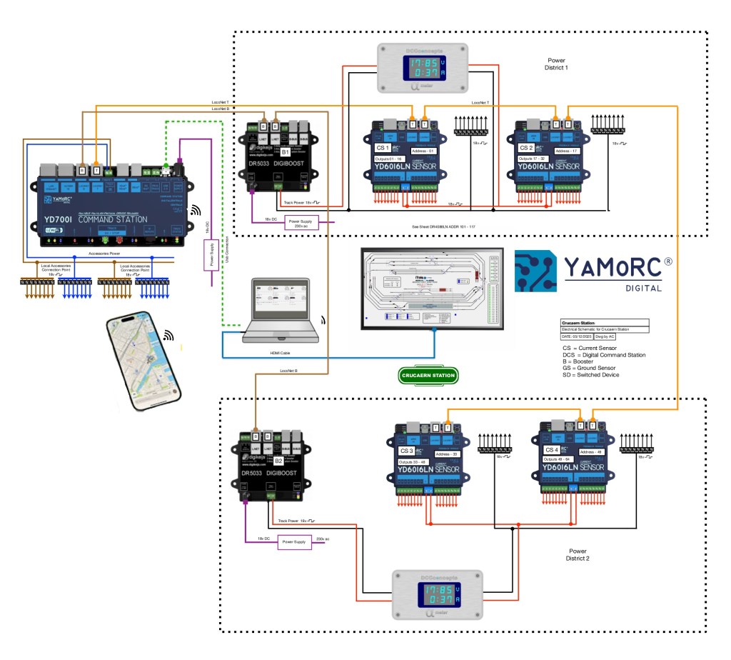
System Description for Crucaern Station O Gauge Layout
The control system for the Crucaern Station layout is built around the YaMoRC YD7001 command station, which provides the DCC command signal, LocoNet communication, and accessory power for the layout. The layout is divided into two electrically isolated track power districts to improve reliability and fault handling. Each power district is supplied by its own DR5033 booster.
Track Power Distribution
Track power within each district is delivered via dedicated red and black wiring from the DR5033 boosters. The two power districts are electrically independent, allowing one district to continue operating if the other experiences a short circuit.
Booster Communication (LocoNet-B)
The boosters receive their synchronised DCC control signals from the YD7001 via brown LocoNet-B cables. These connections ensure all boosters operate consistently and maintain a stable DCC output across the layout.
LocoNet Communication Network
A network of orange LocoNet cables interconnects the command station, feedback modules, boosters, and display units. This network carries system-wide communication including block occupancy data, device status, and accessory control.
Block Detection and Feedback
Each district includes a combination of DR4088LN-CS and YD6016LN feedback modules. These units provide current-sensing and ground-sensing block detection, reporting the presence of trains to the control software via LocoNet. This enables automated operation, route setting, and visualisation on the layout mimic panel.
Accessory Power
Accessory devices such as point motors, relays, and signals are powered using a separate accessory DCC feed from the YD7001. This keeps turnout and accessory operation independent from the track power feeds to ensure stable running.
Power Meter Displays
Digital display units within each power district monitor voltage and current draw in real time. This provides clear visual status information for operators and helps diagnose faults quickly.
Control Interfaces
The YD7001 connects to a computer for layout control software and to wireless devices such as smartphones and tablets for handheld throttle operation. A screen-based mimic panel provides a graphical overview of the entire track plan, including live block occupancy and turnout positions.
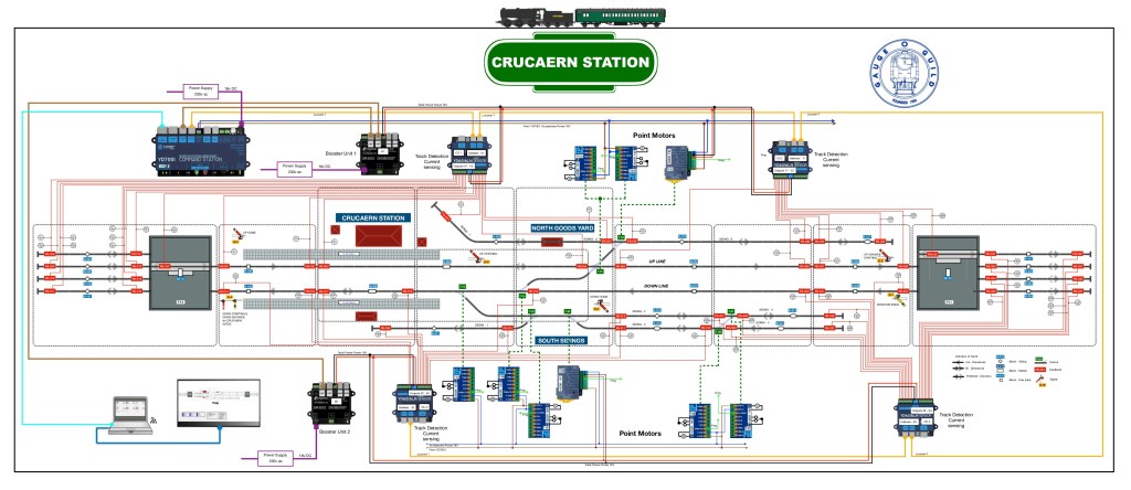
Technical Overview
This layout is divided into two power districts, each managed and monitored to provide reliable DCC operation, feedback reporting and accessory control. The wiring scheme uses a combination of power buses, boosters, feedback modules, point motor drivers and signalling components, all coordinated through the YD7001 command station and LocoNet.
Power Distribution
A pair of red and black solid lines represents the main DCC track bus. This bus supplies traction power to the entire layout. The bus is divided into two separate power districts, each protected and managed independently. Dotted boundary lines identify the equipment assigned to each district.
Boosters and Command Station
The YD7001 acts as the central DCC command station.
It provides:
– Booster outputs (brown lines) feeding the DR5033 boosters via LocoNet B. Each DR5033 supplies regulated track power to its respective power district and provides short-circuit protection.
– Auxiliary power outputs (blue and brown lines) used to feed point motors, accessory decoders and other low-current devices.
LocoNet Communication
All digital communication between devices is carried by orange LocoNet cables, linking the YD7001, boosters, feedback modules and accessory controllers into a unified network. This ensures reliable synchronisation of power management, occupancy detection and signal control across the entire layout.
Block Detection and Feedback
The track is divided into several blocks, each identified by blue labels.
Every block contains two feedback sensors, represented by red labels, providing precise occupancy detection. These sensors report directly to the feedback modules via LocoNet, enabling automated signalling, route setting and train monitoring.
Points and Signals
Turnout control is handled through green-labelled point motors, each connected to the accessory power bus and controlled via LocoNet accessory commands.
Yellow-labelled signals are positioned at block boundaries or key junctions. They respond to feedback events and route logic, ensuring accurate line-side indications for both manual and automated running.
Overall System Function
All components operate together as a coordinated digital layout control system:
– The YD7001 provides command, logic and accessory control.
– The DR5033 boosters supply isolated, protected traction power.
– Feedback sensors deliver block-level occupancy data for automation. Accessory devices such as points and signals respond intelligently to LocoNet instructions.
– LocoNet interconnects the entire system, maintaining consistent communication.
The result is a fully integrated DCC control environment supporting automated operations, realistic signalling and reliable running across the layout.
Andrew also informs us that there are only two boards left of Heyno Junction to wire up before trains can run complete circuits! [Ed. Something I can understand!]

Some lovely modelling.. Not keen on DCC myself, strictly DC in my Train Shed! Looking forward to an open day… please!! Hey-ho* junction is defo one I’m looking forward to seeing in action.
*We’ve always called it this since a trip on the canals
LikeLike