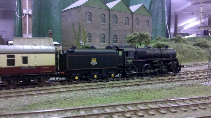
This model was sourced as a lovely second-hand example numbered as 76053 sourced from Ray Heard at the very enjoyable SedgeRail 2018 exhibition. It has the high sided BR1B tender as used by the Southern Region, and best of all 76053 was photographed at Daggons Road – in colour at that! It ran very well when tested on Mira Roads and the plan was to convert it as a ‘quick win’ using Pete Hill’s excellent instructions and photo gallery for the not dissimilar Bachmann 4MT 4-6-0. These can be found on the members only section of the EMGS website. At the base of these instructions is the comment that the method can be applied to other Bachmann outside cylindered locos. A set of wheels (3mm axles for the drivers) for the loco together with a set of crankpins and washers to bush the coupling rods were ordered from Alan Gibson. These were swiftly delivered and destruction duly began.
Tender
At this point I intended to use the Bachmann tender wheels per the instructions, but found that I was unable to achieve a back-to-back setting that cleared my test pointwork in any sort of acceptable fashion. In the parts box was a set of rather nasty plated zinc wheels from a DJH 4MT 2-6-0 kit from the 1980s; these when fitted worked well enough through my pointwork. To be honest the effect was a little rattly compared to a tender with a twin beam compensated Perseverance chassis (as on my Black Motor) – but this is supposed to be a quick win. When checking the ride height it was found to be 0.5mm too low and the wheels proved to be 12mm diameter when they should be 13mm so the correct wheels were ordered from Alan Gibson and subsequently fitted.
Loco
The Loco was carefully dismantled (watch out for the delicate reverser control rod which pulled out in my case). I also found that the pipe work under the cab was glued to both chassis and body so something had to give and it was the pegs into the chassis that broke. Forewarned, the pipework could probably be separated in a more orderly fashion. Probably because of this extra glue the body was harder to remove than suggested in the instructions.
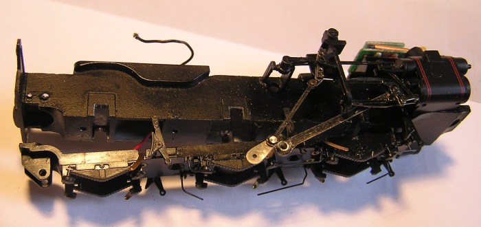
Also wildly different from the 4-6-0 is that the keeper plate is wired not only to the motor at the rear, but to the DCC chip in the smoke box. I thus had to unsolder the wires from the motor and then remove the motor so that I could extract the wheelsets past the wires to the motor. The gearbox was also removed (two screws) so that I could feed the wires back to the motor when I had finished .
Pony Truck
 A further departure from the instructions is that the 2-6-0 has a pony truck rather than a bogie, however the pony truck wheels do indeed just pull out and the Alan Gibson replacement wheelset can be fitted spaced out as per the instructions for the 4-6-0 bogie using 1.5mm lengths of Biro tubing or similar plastic tube.
Wheels
 The wheels on the 76xxx are smaller than the 75xxx with different counter weight pattern, appropriate weights were cut from .010″ plasticard with an Olfa compass cutter using the rather nice Bachmann wheels as patterns. Note that the weights are not symmetric with the cranks! I filled the space between the spokes behind the weights with epoxy putty, but that’s just me really. Due to the very narrow frames I needed 2 mm of washers each side of the leading and trailing driving wheels, and 1.5 mm of washers each side of the centre driving wheels.
Coupling Rods
 Oddly I found the holes in the coupling rods far too large for the Alan Gibson (AG) washers so fabricated my own by soldering some 3/32″ brass tube into some 1/8″ brass tube and turned the outside diameter down to an interference fit in an electric mini-drill using files. The end was soldered into the rods, cut off nearly flush with a saw and filed flush with a file.
Dummy Mainframes
 One of the characteristics of the 76xxx class is that the frames are very close to the wheels. With a 00 chassis and EM wheelsets there would be a substantial gap behind the wheels so the chassis was measured up for a set of dummy frames that were drawn up in QCad and printed out on paper for a test fit. Adjustments were made to the drawings and the process was repeated until a good fit was achieved against the various features on the chassis and keeper plate – these not being entirely symmetrical across the loco. The dummy main frames were then fretted from .030″ Plasticard using the printed paper patterns stuck to the plastic using a Pritt stick glue – Pritt worked extremely well for this task. I think .040″ would have been even more suitable had I had some to hand. The dummy sides are not glued in and are retained by the keeper plate.
Problems, Problems
It was at this point that a potentially simple conversion got a bit complicated. For some reason I seemed to have had a batch of AG crankpin nuts with insufficient thread together with what seemed to be a variable selection of AG crankpins of uncertain age. I found that the threads on any of the wheels would strip for a pastime particularly the threads on the new return cranks which have to be removed and refitted several times to remove small amounts of material until the position of the return crank is correct. What to do?
I rather liked the Markits deluxe crankpins that I used on my Black Motor conversion. To use these I would need to tap a 10BA thread into the AG wheels and yes, reference to the Interweb indicated that at least one person had done this successfully. So the wheels (still on their axles) were removed and the holes opened up gradually to 10BA tap size and then tapped in my mini Expo stand per the Black Motor.
Now dear readers plastic is much softer than metal and too much vertical force was applied to two of the wheels resulting in the thread not being properly formed. To fix this I had some 2mm OD brass tube that would take a 10BA thread. This was soldered into a short length of 2 mm ID tube that I could put it into a chuck without distorting. I was then able to drill and tap a suitable thread. Cut to length these inserts were superglued into holes opened out to a tight 2mm diameter.
With the deluxe crankpins fitted were my problems over – no they were not! The new crankpins are quite a lot bulkier than AG ones due to the boss with the slots used to insert them. This meant that the coupling rods need to be as thin as possible and the excellent deluxe crankpin nuts also thinned to match. I also had to gently bend the bottom slide bar out of the way to avoid binds. For the centre driver I used an AG bush on the coupling rod and followed the instructions to remove material progressively from the Markits crankpin nut until the return crank was in the correct position. Only at this point did I rivet the combination lever to the return crank.
Drawbar
The tiny buffers on the tender were removed, but there seemed little scope to drill a new hole in the drawbar per the 4-6-0. Therefore a new drawbar was fabricated from nickel silver with the holes at appropriate centres for 3’6″ minimum radius.
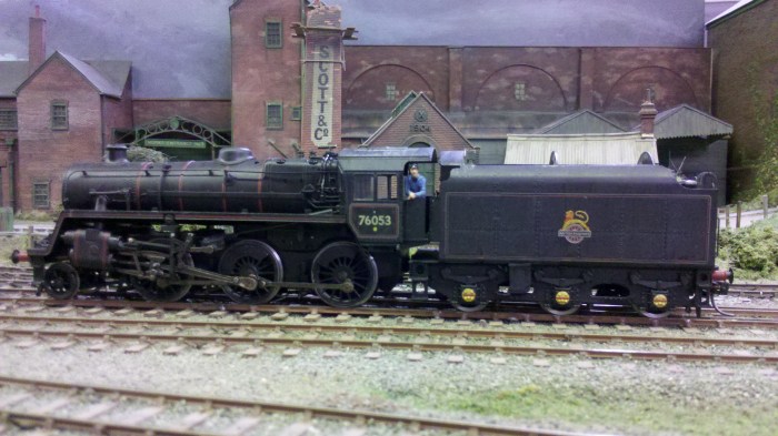
Let down with a bit of grime, but needs more.
Reassembly and Testing
In all other respects I was able to follow the excellent EMGS instructions. The Loco was re-assembled without great difficulty and has proved to be an excellent runner successfully hauling passenger and goods trains at our 2019 Open Day. Without compensation it rides a little heavily, but it stays on the track and has good haulage capacity. It also still looks great, even more so now that it has been lightly weathered.
Footnote on Crankpins
The next engine into the workshop was a Crownline BoB pacific that needed re-wheeling with AG Wheels after a crankpin sheared off one of the original Sharmans. This time good quality (but inexpensive) 14BA C/S steel set screws were used as crankpins. Loctite being used to secure the crankpins into the wheels. A thin washer was placed between coupling rods and wheels, and the coupling rods secured with Markits Deluxe Cranknuts filed to the correct length for clearance. This turned out extremely well, feels properly engineered and will become my future standard for all conversions.
