By Bob Alderman – November 2010
I often recorded the build of a loco, wagon or building to show a client the progress and potentially write an article about it. Here is one I built for myself – a JLRT 4F. The kit was imported into their range from, I believe, the Underhill range. It was upgraded by a resin cast boiler and tender body and many brass castings. The remainder of the etched parts were unchanged.
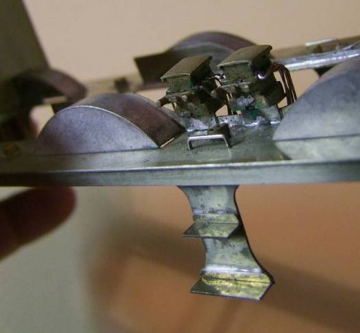
Tender Chassis.

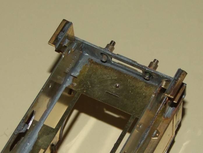
Followed the instructions but as I wanted to use split axle pick up on the tender this led to making insulated bushes. The design does not readily allow the use of any of the commercial horn guides!

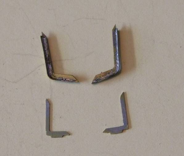
Note the addition of guard irons at the rear. There are none in the kit and have to be made.
Tender Body
The tender body followed. No particular problems unless you fit hand rails at this stage. They will not allow the coal space moulding to fit!
The tender buffers need a lot of cleaning up and soldering the stop is a challenge.

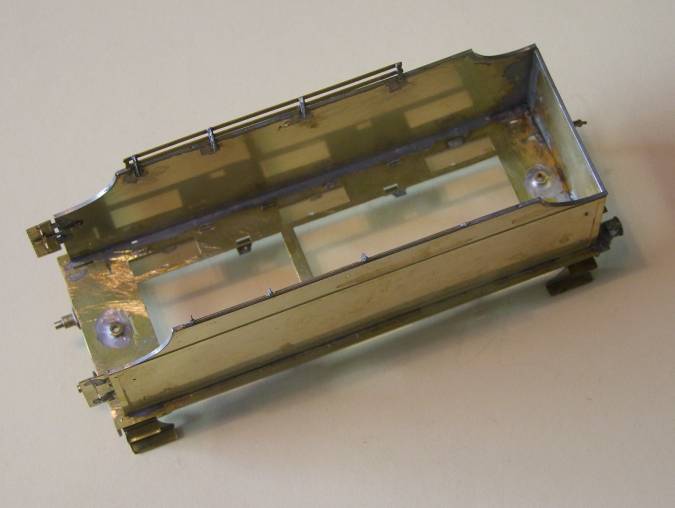
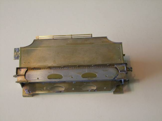
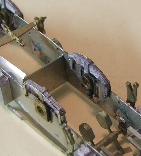
It took me while to recognise the chassis stays that fit across the frames beneath the cutouts. Once found, OK but still some unidentified parts that may be associated with them. Not fitted, not missed. Note the front stay above and next to the cutout and the rear is below and next to the bottom of the frame. As these stays stop the chassis from being removed I will be screwing them to the brackets on the frames with 16BA screws.
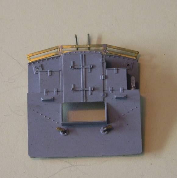

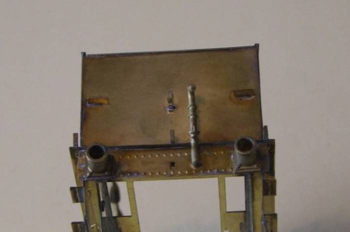
The tender front requires the addition of the fire iron restraint. It’s there even without the coal rails. I noted in one picture they are attached to the coal rails. The lifting eye reinforcing added on the back and two water cock levers to the front. These I made from brass wire flattened to make the handle. There may be castings but I haven’t recognised them.
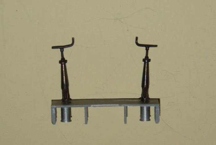
The platform that the brake and water scoop columns are fitted to has to be reduced in height from the moulding provided. Use the column extensions to set the height. I used a fine fret saw to cut off most of the excess than carefully rubbed it down to size on a sheet of wet and dry. The standards are upright when fitted against the front bulkhead – honest
The bulkhead at the rear of the coal space is straightforward.
I had to modify the coal space as I wanted the tank vents outside the coal space. The moulded detail was carefully removed and the holes filled, perhaps unnecessary as they will be lost under the coal. Small idents are provided as guide for the holes for the rear position.

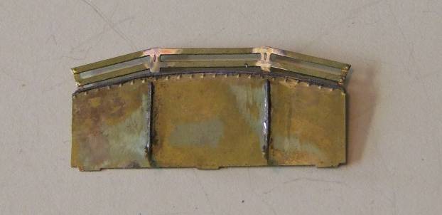
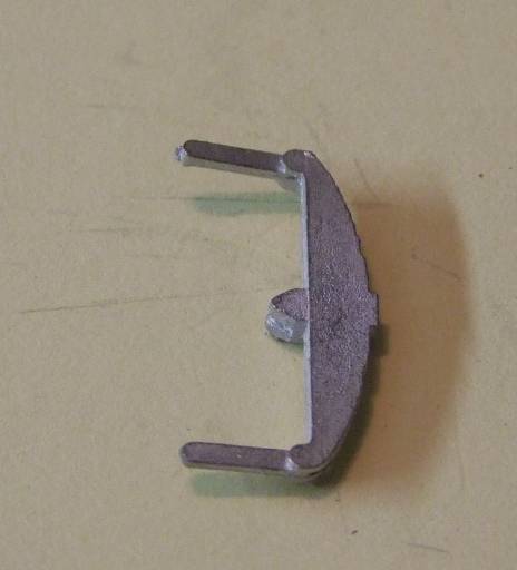
There are four internal support brackets that fit the coal space.
The top two fit on the coal slope approximately shown by the yellow arrows and the two right angled ones fit on the top where there is moulded detail – red arrow. I had to make a second one of these. I may have lost it from the fret but I think actually only one is provided.
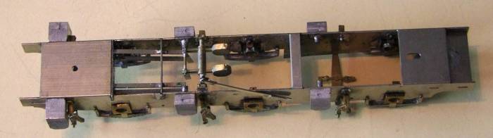
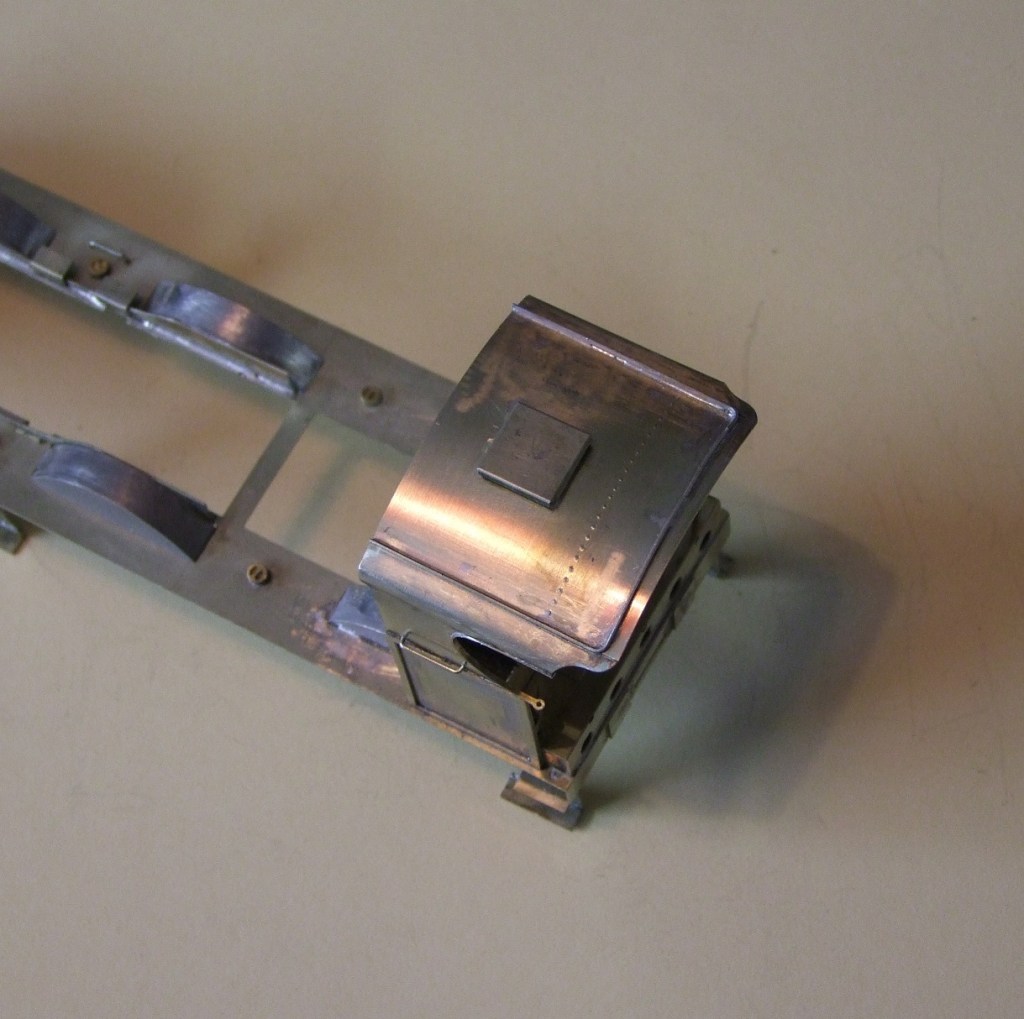
Locomotive Chassis.
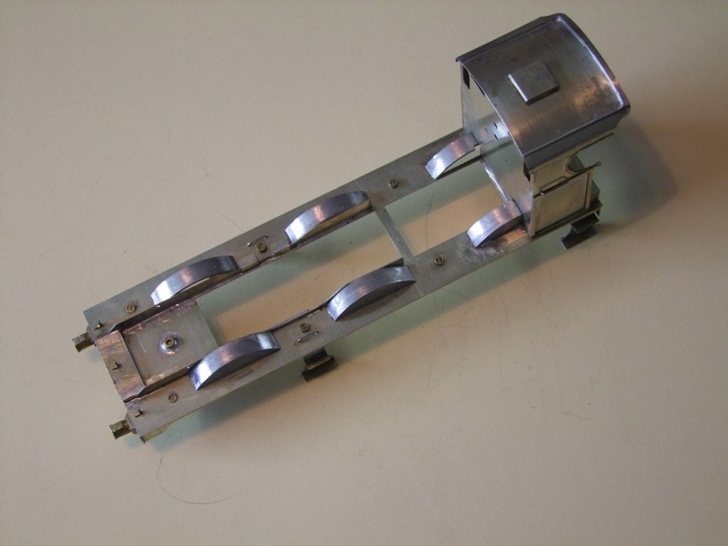
This folds up readily, perhaps a little scoring of the fold lines may help it fold square. Where tabs for frame spacers fit these may have to have the slots cleaned out to allow them to go home completely. If not the chassis side will bulge a little.
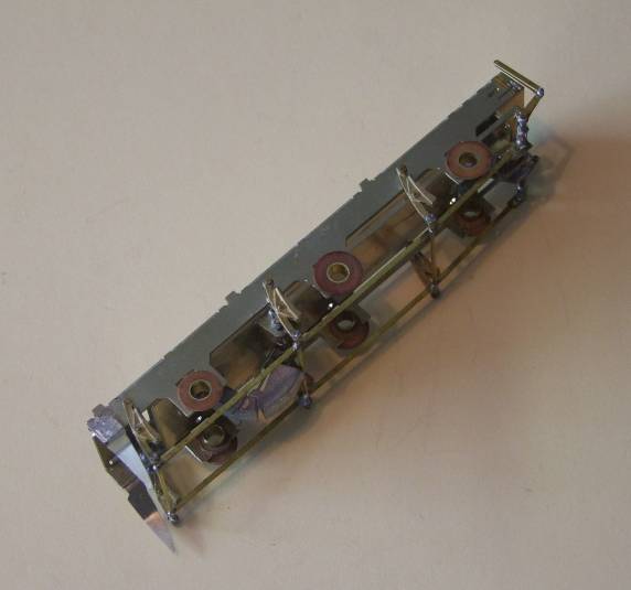
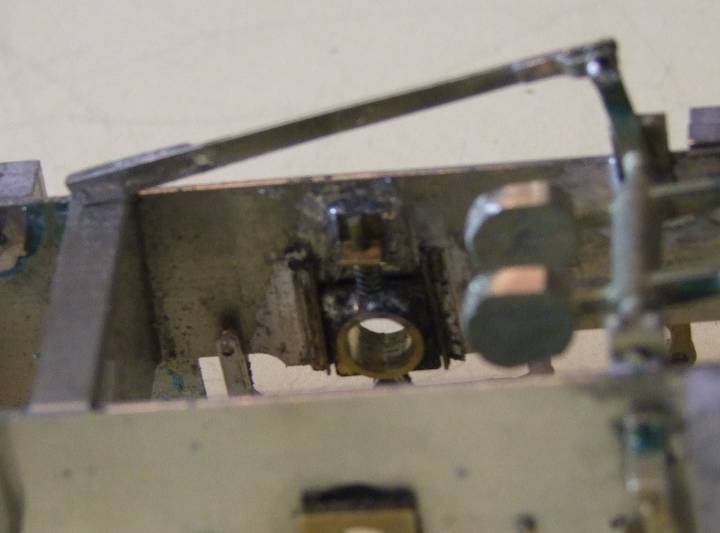
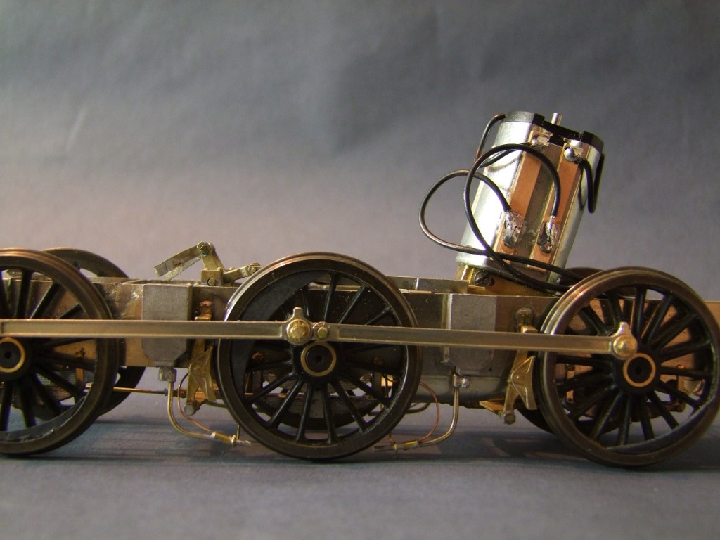
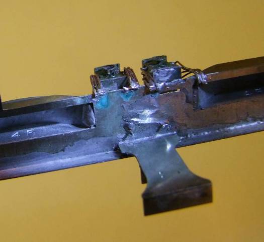
The loco chassis had no provision for suspension, and this is a feature I must have. I noticed that the holes provided where the same diameter as the slot diameter on a Slater’s square bearing. I have elongated the hole to the bottom of the frame to allow these bearings to slide in.
These are the bearings that are normally used in hornguides, and they were modified with the addition of a spigot to fit the springs.
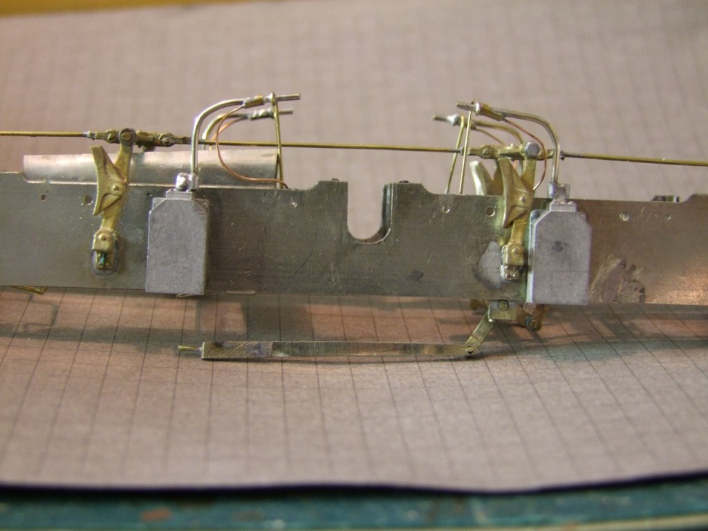
The round holes in the chassis were elongated downward to form slots.
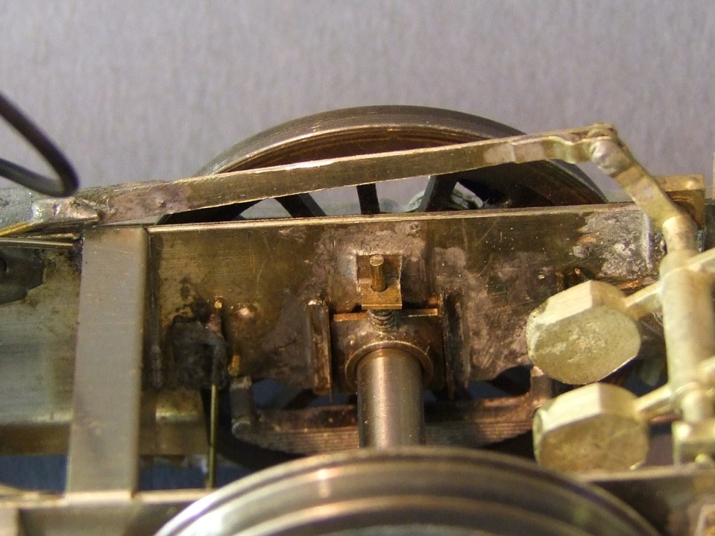
Vertical guides were added from milled brass angles. Tricky soldering these on. The bearing had to be in place to help locate them yet not soldered too. A small bracket is fitted above to allow a stem soldered to bearing for the spring to run on. After doing all this six times it became easier!
I wonder if the holes are too small as provided. They will need a lot of opening up to fit the plain bearings in the packet of turned items.

The leg on the cast spring fits inside the frame when laminated to the etched spring. If fitted with a screw then a hole is required at the end or it trimmed short.
The laminates of etched and cast springs are attached with 16 BA screws and serve to retain the bearings.
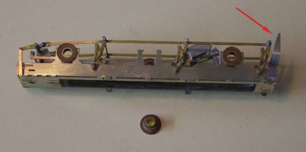
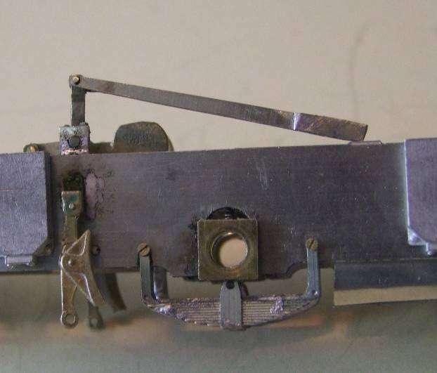
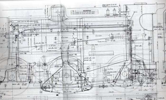
NOTE. Unless you fit the optional inside valve gear no weigh shaft and balance weights are provided. No etched ones at all. I prevailed on JLRT to supply the casting with the bearing blocks, so I could fit this prominent feature. Note too that the etched reverser reach rod is incorrect. It is straight not curved. See copy of GA taken from the Wild Swan profile on the locos.
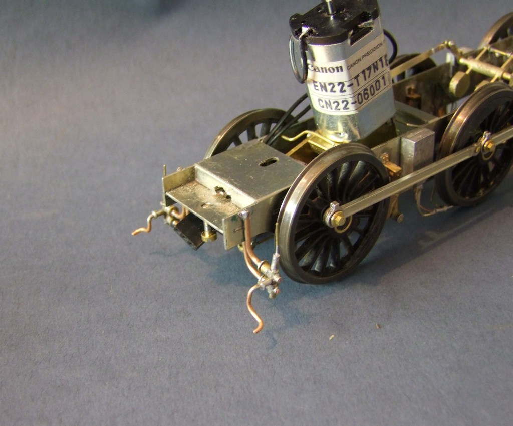
The motor was fitted to the third axle as it had fit within the firebox. There were nice cast brakes and the sand boxes were clean.
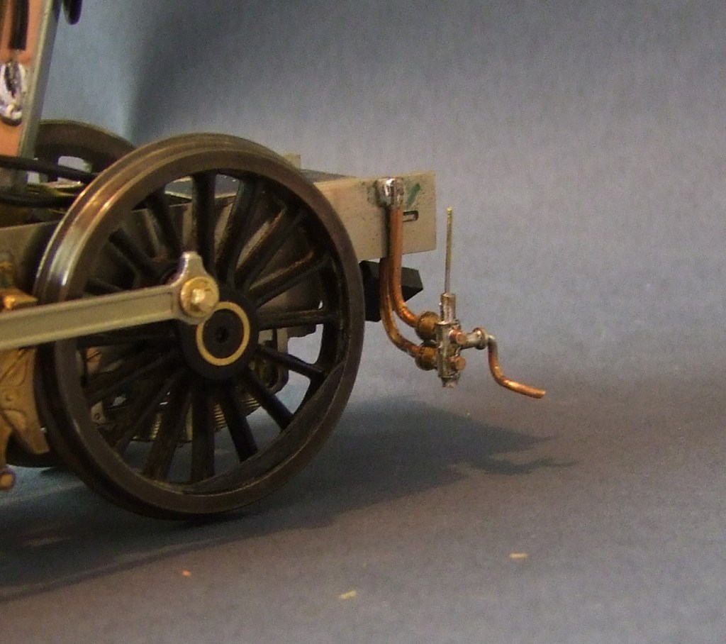
The pipework was scratch built from wire.
The Footplate and Cab
I found that this was short on some detail.
There are some quite prominent rivets at the front of the valance, certainly later in the locos life. Similarly though there are castings for the piston tail rod covers there is nothing for the patch that fitted when they were removed; again a very common, or universal, feature later in life. I left fitting the splashers until all the soldering of brass and nickel silver components was completed.
Turning the bend in the top of the cab sides requires care. Something to form the bend over is essential whilst clamping the side. I have a bending tool that was made for me that makes such bends easier. It required several moves annealing each time.
A small hole is needed in the spectacle plate to allow the whistle control to pass into the cab.
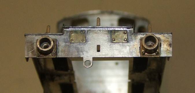
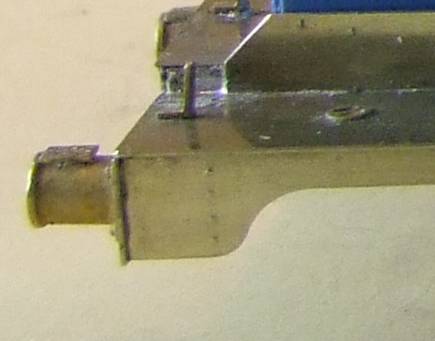
Front buffer beam with tail rod blanking plates.
The illustration of the lubricator mounting in JLRT instruction picture seems to be the reverse of my interpretation of the picture in illustrating them in the Wild Swan profile. The riveted flange is on the outside of the false frame on the footplate with the horizontal part towards the inside.
A lot of detail parts were added to the footplate; lubricaters, reverser, injectors and more.
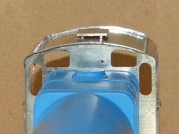
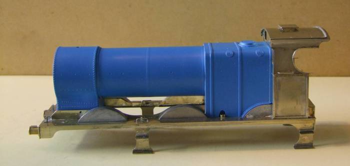
Boiler
Next came detailing the boiler. Not so easy as it would first appear. The boiler is a very detailed resin casting, quite heavy as it appears to have a metal weight cast into the barrel.
The interesting part is drilling holes into it. The resin has a fine glass fibre content that blunts HSS drills. They will drill the first hole; barely the second and the third not at all! I turned to carbide drills. They are inevitably more expensive and easier to break, but they don’t blunt. I also purchased a burr to remove material from under the smokebox to clear a nut. As it is some time since I made the model I can’t remember if I removed material from inside the firebox to clear the motor. If creating dust with this material a mask is advisable. A slot had to be made in the firebox where the reverser reach rod disappears behind the cladding. I think I used a drill and joined up the holes.
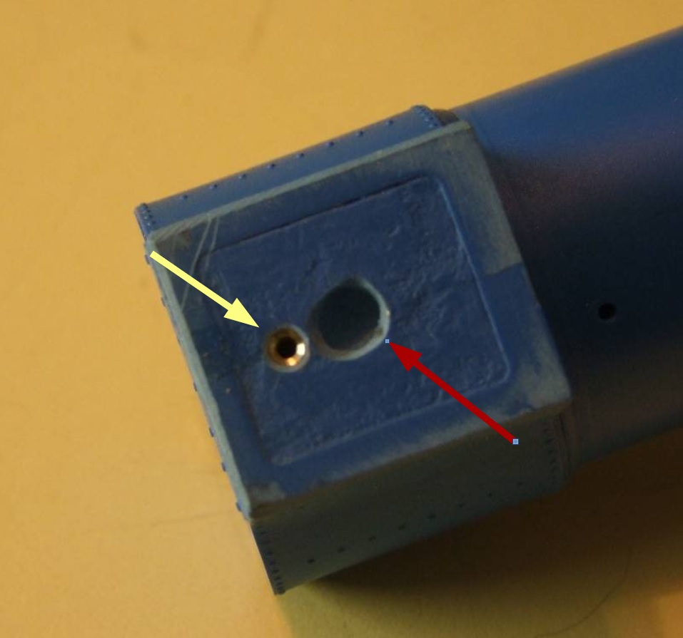
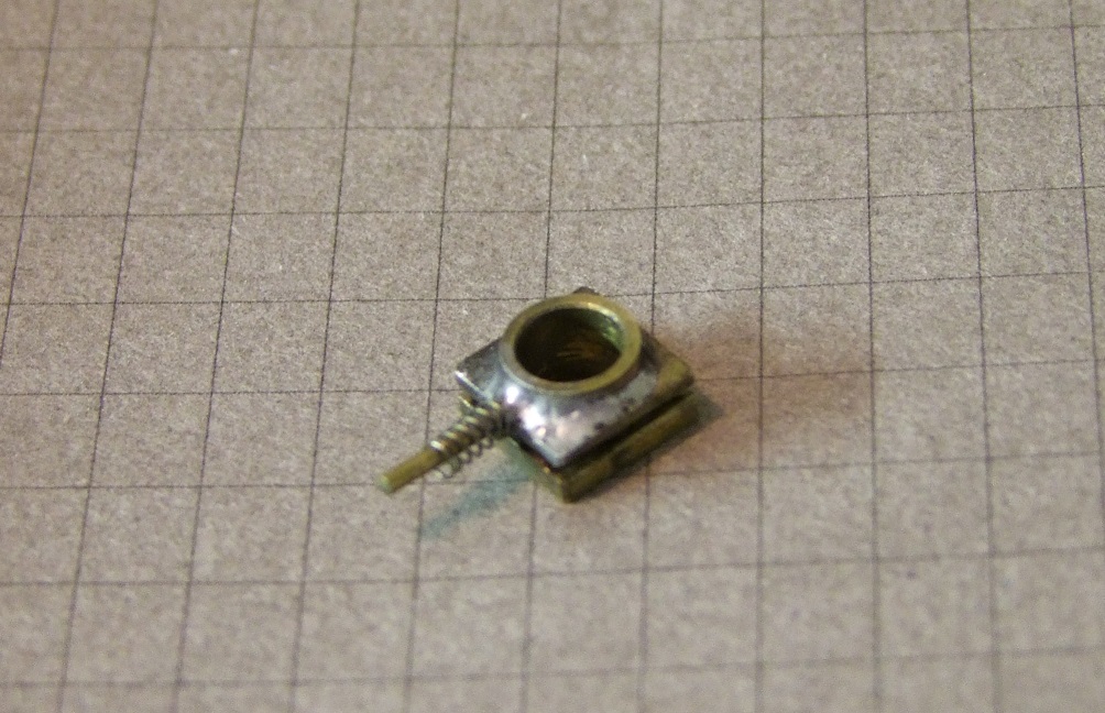
The boiler moulding needs a relief to accommodate the chassis fixing nut soldered to the footplate – red arrow. In addition, I bonded in a barrel nut to screw the front of the boiler to the footplate – yellow arrow. This is drilled from a corresponding hole in the footplate. I am unhappy about bonding the boiler irrevocably to the footplate.
Part 2 can be found here:
Bob Alderman
November 2010
