A description of constructing the kit
Bob Alderman © 2012
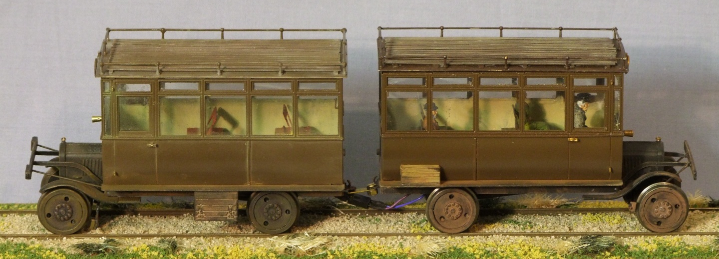
This is an account mostly of the construction of the un-powered car of the pair – I was asked to write this after completion of the powered version! Notwithstanding the latter will also be covered.
By and large I have followed the comprehensive instructions as they are written. Similarly the kits have been assembled as provided with one exception. That being the front axle mounts.
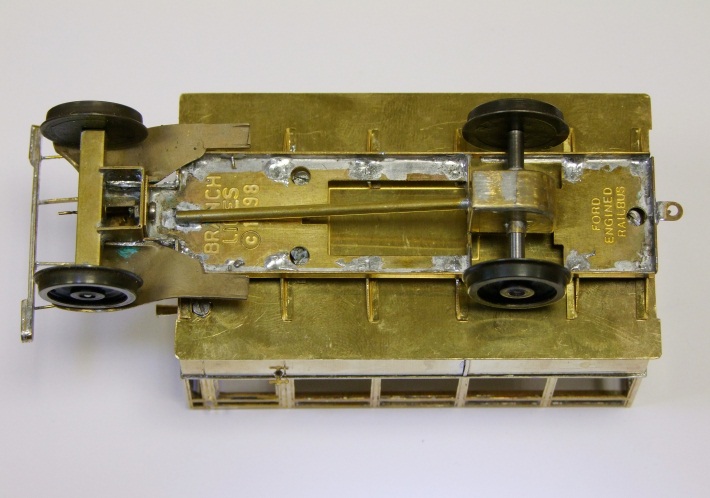
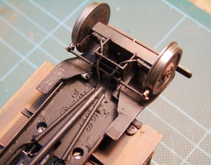
The basic chassis was folded up. Next comes the rear axle mount and the “drive shaft” that stabilises it on the motor mount, and after that the floor brackets. The locations for the small ones are small and they tend to come where they want. So once nominally in place the chassis was inverted onto a flat surface and the soldering iron re-applied at each joint so the brackets moved to touch the surface. The larger cross members provide the datum setting. A little poking around was needed to ensure they were not twisted. On the non-powered version the top of the motor mount was remove to flush with the underside of the floor. In the case of the powered version the resetting of the brackets was done in two parts; ahead and behind the motor mount. The motor mount has to be off the flat surface used to set them.
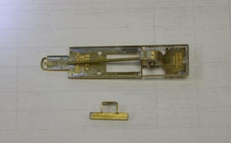
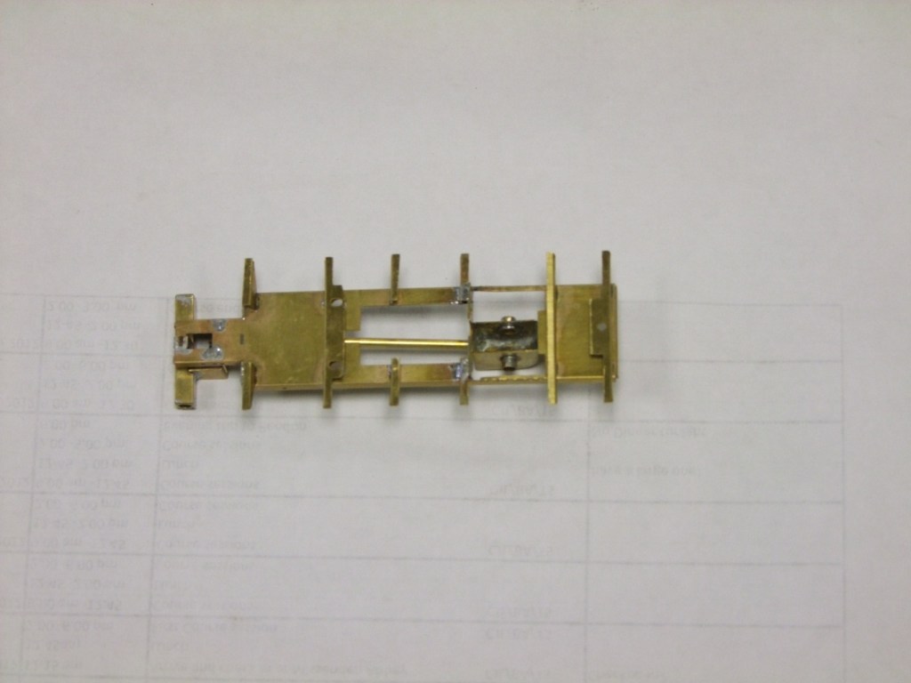
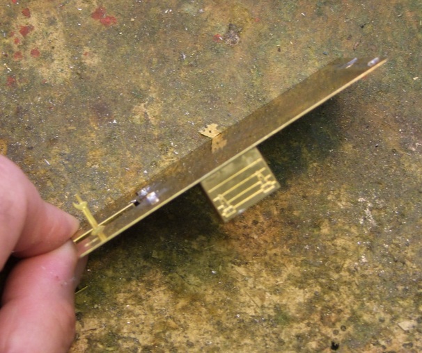
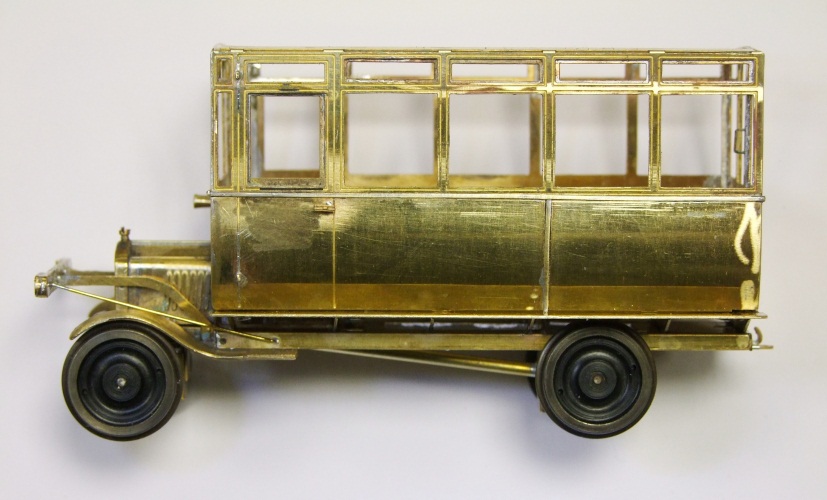
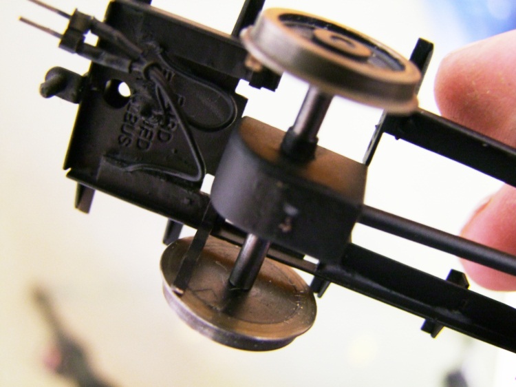
The front axle mount can be seen in both pictures. Rather than assembling the three bent-up channels provided I elected to change them for length of 3/16” square tube. Inside this were soldered two 1/4” long 1/8” bore brass tube as axle bearings. The mount to the chassis was trimmed, removing part of the lug that had the axle holes. Two saw cuts were made in the tube to locate the mount.
Folding the bonnet proved far easier than expected. The sharp top bend is a half etched bend line and the sides naturally curve between full and half etched sides to match the radiator grill and end plate. The hardest part is fitting the wire hinge along the top. I found it easiest to tin the wire and push it to the apex with the soldering iron.
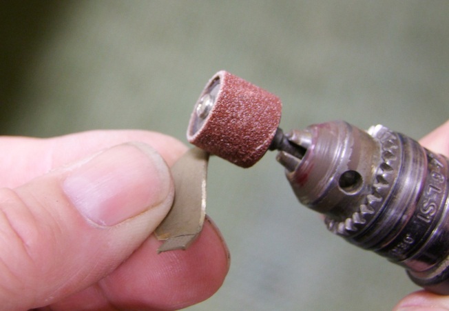
The mudguard detail (mudguards on a rail vehicle?) followed by the buffer beam. The mudguard castings needed some fettling to remove the runner attachment and to improve the look. Mainly this was chamfering the edges to suggest they were made of much thinner material. I used an abrasive drum in the modelling drill for this.
On this vehicle I was able to fit the long stays to the outside of the buffer beam. On the first, powered one they would not fit over the mudguards without a bend. The controls and driver’s seat completed the chassis.
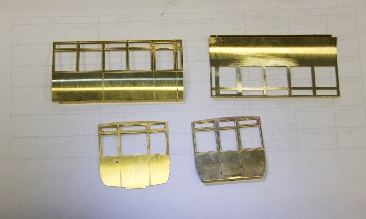
The body followed. The turn under on the sides required rolling bars to form it. It is full thickness etch. The trick of pulling a side around a bar with tape would not work.
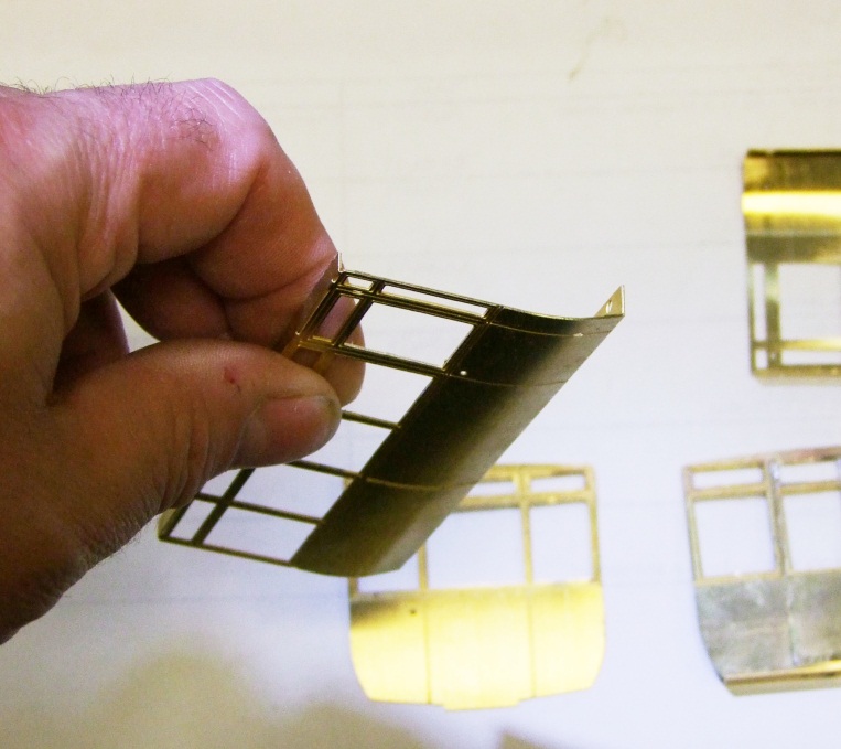
The curves were “adjusted” by gentle pressure to flatten them until they matched the ends. Once matched an end and a side were initially tack soldered together. The horizontal etch lines on each were used as the datum. With a satisfactory match a complete joint was made. In the area of the window frames a minimal solder fillet was needed to maintain a land for the attachment of the glazing later.
The second side and other end were joined. I now had two “L” shaped parts. These were then joined in the same way as the first joints.
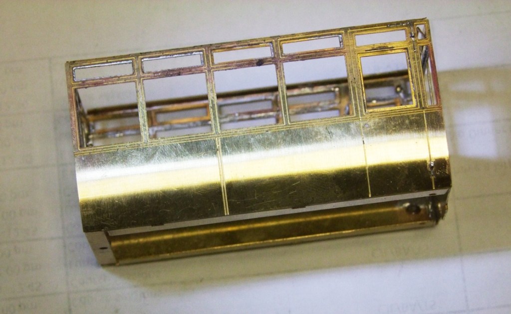
The small window doublers were added. I elected to have an open one at the front; this can be just made out top right of the picture. Door hinges from fret edges were added as were the door handles.
The floor followed, not much to do here except fold down the sides of the driver space, add two nuts, the brake handle and the box under the floor. For the latter you need to offer the floor to the chassis to best determine its position. At least one support angle has to be slightly shortened so the box sits inside the edge of the floor.
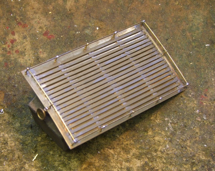
The roof completes the assembly. Whilst in the flat the holes for the handrail knobs were enlarged to suit the shanks on the knobs. Rolling bars were used to produce the, albeit small, curve. Again the metal thickness makes alternative methods like rolling it on the carpet under broom handle not so easy. Annealing may be option for those without bars, for the sides too, but there is the bother of cleaning off the oxide film.
The curve was matched to the ends and the small fillets added to the underside of the roof at the ends. As wanted the roof to be removable the next job was to create its location and fixing. For both vehicles there are small spigots fixed to the roof that fit in holes in the top angle of the sides. Serendipity meant that the spacing straps for the roof lathes sit over them both hiding the ends and preventing them from pushing through.
The lathes complete the roof detail. Initially I added the one on the centreline them from this set a distance for the outer ones by dividers, and the filling in using dimensions set by the dividers. This did not work and I ended up with uneven spacing. So I re-read the instructions…
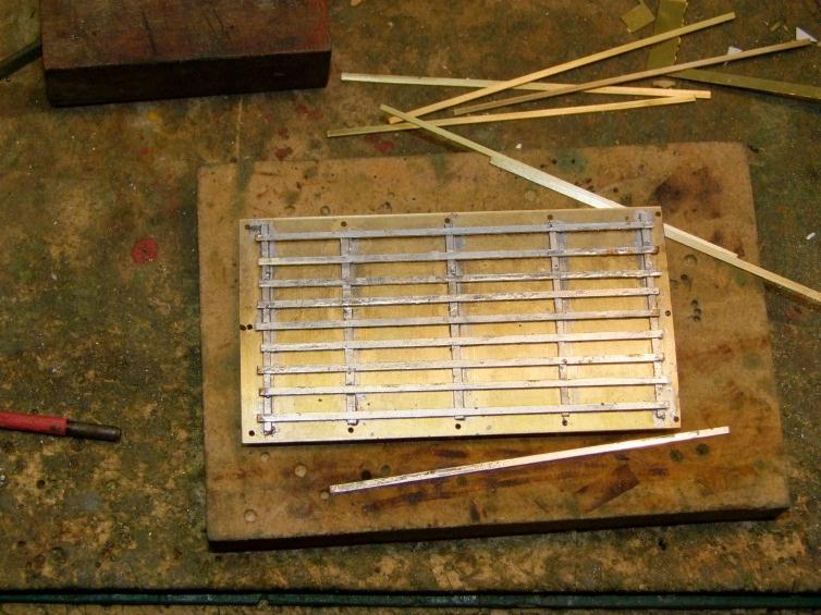
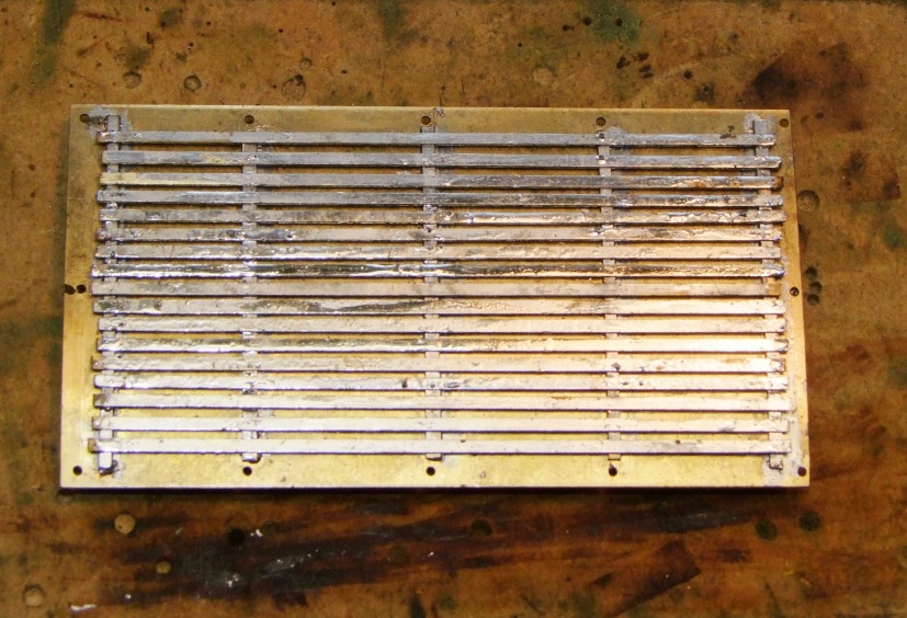
The one on the centre line is fine the two outer ones were set from the edge. Next another was placed by eye halfway between and so on, placing a lathe in the middle of each gap left; one side then the other. This has resulted in a much more even placing of the lathes. A slight unevenness of the ends was corrected by filling. A strip of spare etch was slipped under them to protect the roof whilst doing this. Excess solder was removed by scraping and abrasive block.
I added the handrails next. I have elected not have the curled ends for two reasons. I liked a more austere finish without and, if they were there, the curved rails at the ends have only a single knob holding them with the ends butt jointed to a corner knob carrying a through wire. Therefore the curved end wires are located in three knobs, the straight sides are also located in three knobs and their ends butt jointed at the corners. The ends of the knobs projected through the roof and had to be trimmed flush.
A headlamp completed the roof.
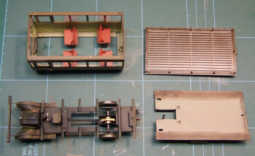
All the parts were then joined as final check before painting, though I seem to have missed off the roof when photographing it.
You will note at this stage the wheels do not have their finishing discs and bosses. As they are fitted with superglue they were last thing to go on having established that the vehicle runs well. The glue locks on the wheels precluding any future easy removal.
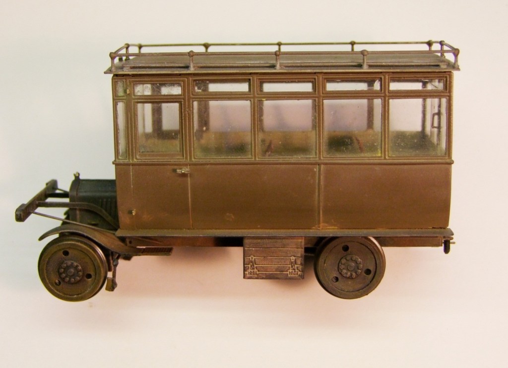
Happy with everything the vehicle was broken down to its main assemblies cleaned, primed and painted. I use a kitchen cleaner Barkeepers Friend as my principal cleaner (good for stainless steel in the kitchen too). The parts are washed in hot water then whilst wet the cleaner is sprinkled the paste that is fomed scrubbed into the parts with a toothbrush or short bristle brush for the corners. It rinses away with more hot water. When dry the painting commenced.
I used Halfords acrylic Grey primer for all the parts. The chassis was finished in their matt black and the bodywork and roof in Rover Maple. Though gloss it is not too shiny for the model. The interior is painted a cream up to waist level; brown above. The seats are deep red.
Glazing followed from the ample supply in the kit. It was cut to size for the various windows and glued in with Canopy Glue from de Luxe. This was found in the local aeromodellers shop. It sticks well and dries transparent. Any oozing at the edges can be removed first with a cocktail stick then with a wetted cotton bud. If the glue is left to dry to where it starts to go transparent there is less less problem with oozing.
The components were reassembled, the wheels were finished and it was weathered. I have used a mixture of dry brush and powdwer to add age to vehicle.
On motorising and pick-ups.
The powered version differs by needing a hole cut in the floor to clear the motor. This is defined by a half etched line. In spite of following this I found the clearance at the motor brush connections tight and locally enlarged the gap to clear.
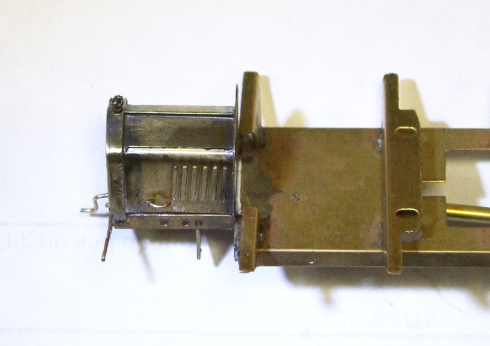
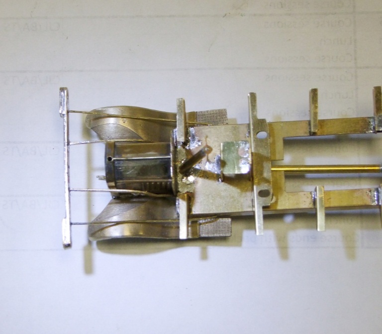
The motor mounts to the plate that the rear axle mount is attached to. The axle mount carries the bearings and hides the worm wheel. The worm wheel is included in the non powered vehicle too as it locates the axle. I had no fiddling to get the gear mest correct. The fixing located the motor at the correct height.
On the powered version I have fitted pick-ups to all four wheels. One the rear pair it is 0.5mm brass wire attached to copper clad sleeper strip. At the front the same strip is fixed behind the axle mount with phosphor bronze strip bearing on the wheels. The wires from these are led through small bore tubes to the motor to keep it tidy.
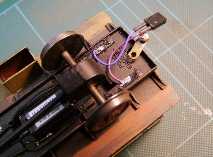
As well as the pick-up the picture shows the connection to the un-powered car. Added after painting. The tow bar needs paint and the wires need a controlling device.
On the un-powered car the pick-ups are phosphor bronze strips rather than wire. I fitted this as it has a lighter touch than wire so is less likely to slow a wheel driven from the rails.
