Locomotive Chassis
The smooth rolling chassis of DaveS’s 7mm Black 5 was the featured image in the February 2021 Blog and was shown virtually complete in our April 2021 Blog. What follows is how this came about in our hero’s very own words:

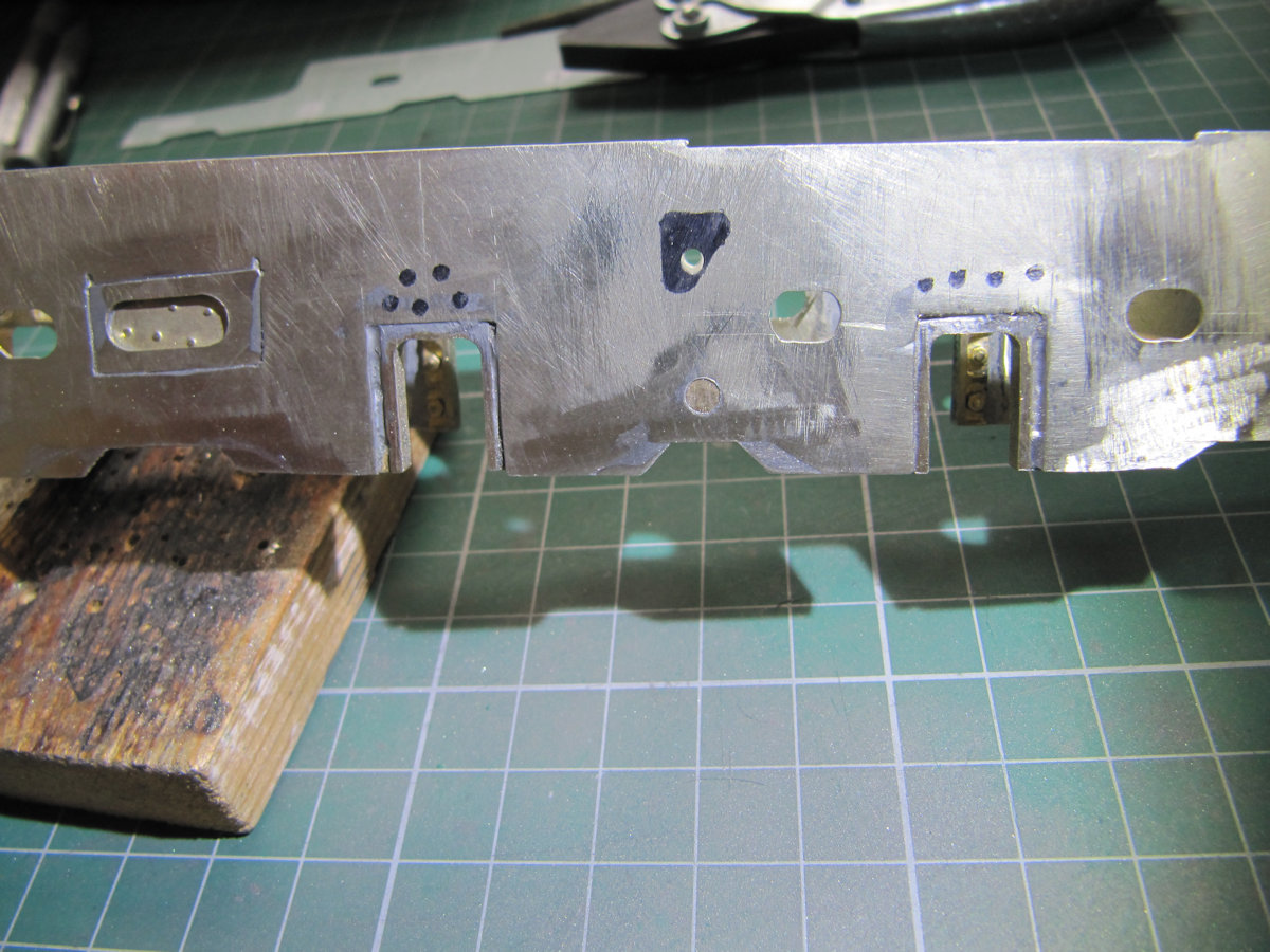
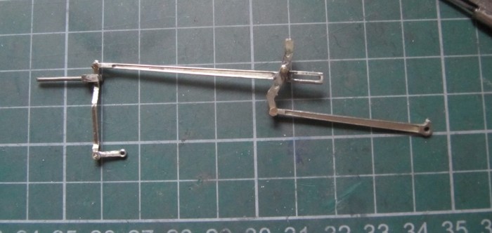
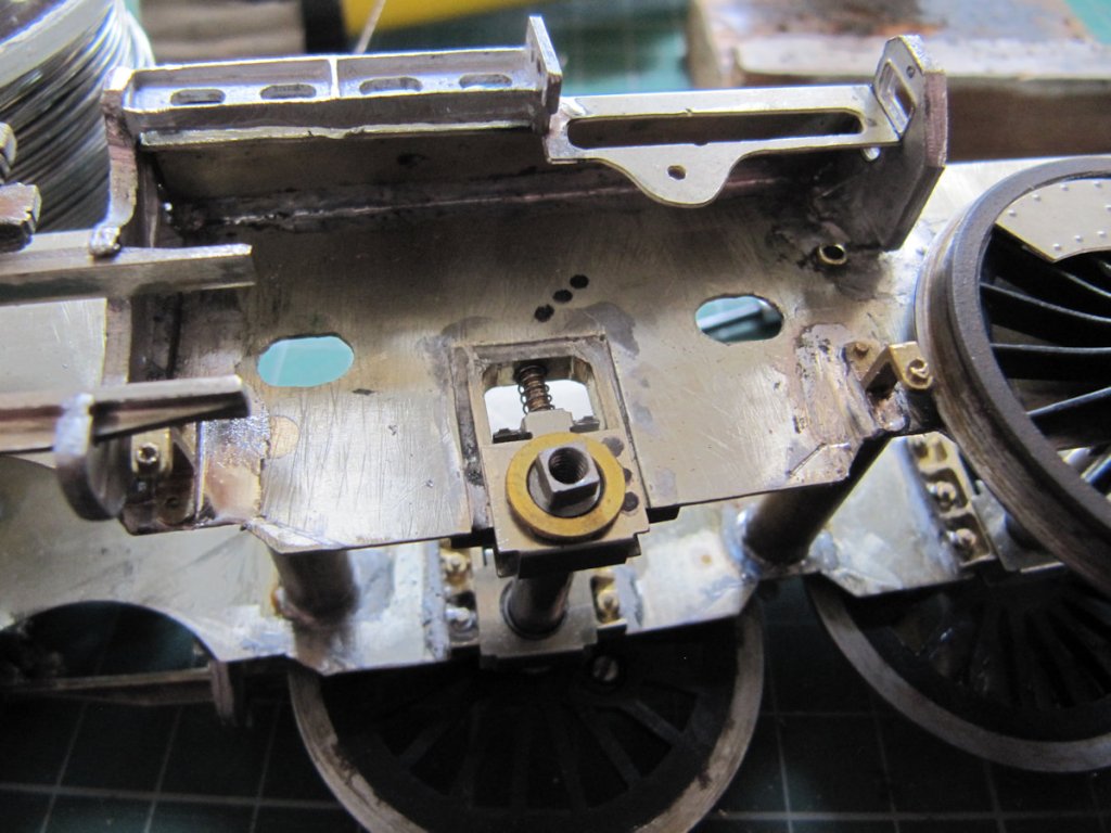
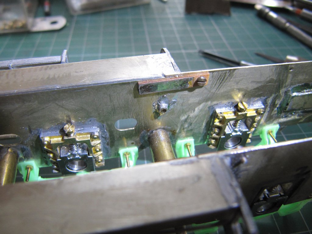
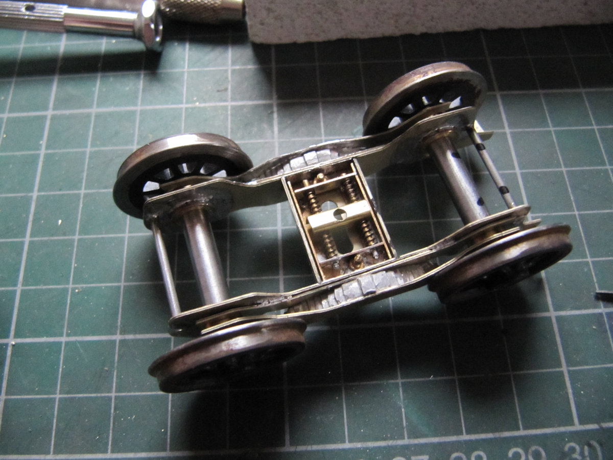
Best start with the frame modifications. Small filler pieces were cut from the etch that the frames came from – correct thickness. These were soldered in place and filed to shape. The extra holes in the frames were also removed apart from the black triangle in the second picture. I decided not to cut that out as I’d have to make up extra supports for the Weigh Shaft that uses the small hole.
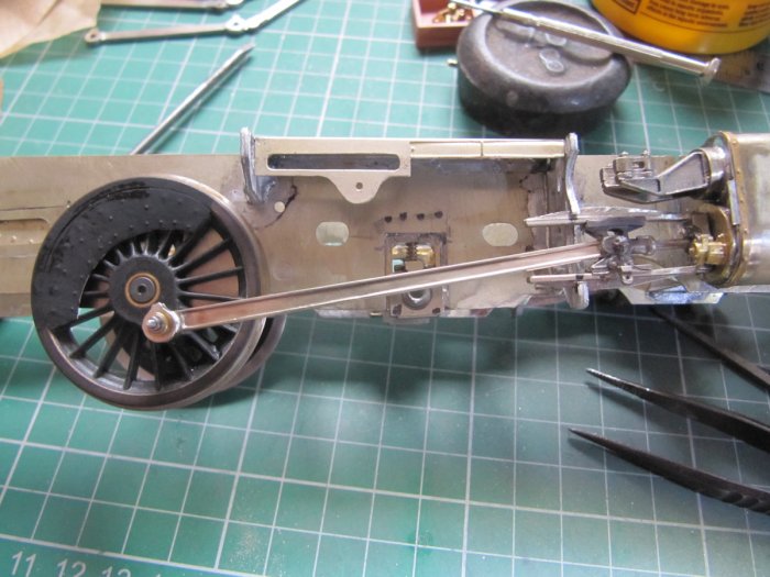
Once that was done the slide bars and their support casting were attached. The slide bars had already been fettled to ensure that the crosshead slid nicely in them. The support casting was modified to accept the slide bars. I did not attach the slide bars to the support casting, I did not see the need. Assembling the connecting rod, crosshead and centre drivers we find that it all works well with no binding.
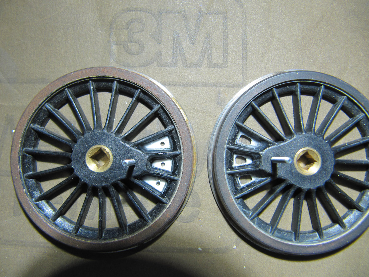
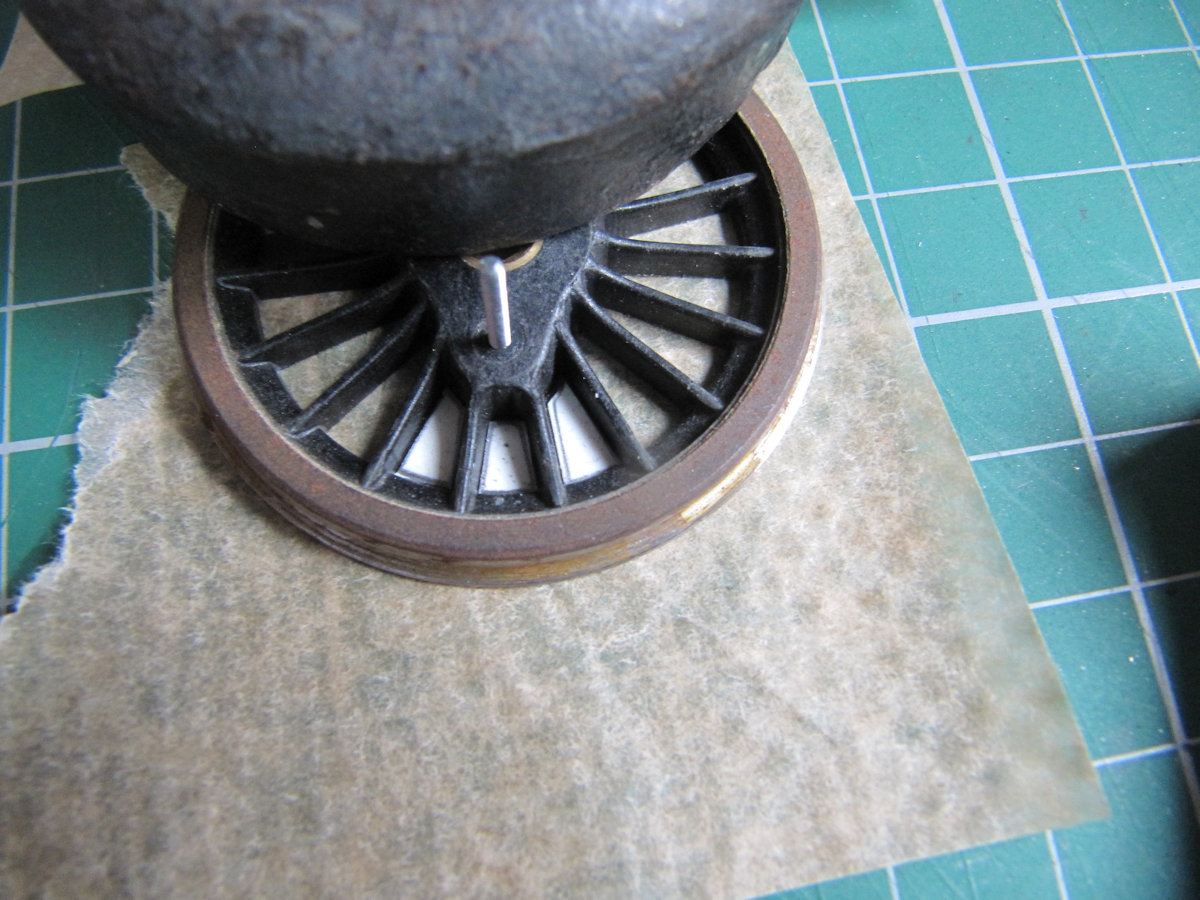

The centre driving wheels (on my prototype) have stiffening webs round the crank pins. This detail was added to the wheels along with the balance weight etchings. Note to self, do not use the thick end of a cocktail stick to paint with – a brush may give better results.
Looking ahead one wonders about the best way to attach the return crank to the crank pin. Reminded by Keith, I looked at Bob Alderman’s instructions when he did his 8F. “Solder a Tapped Top Hat Bearing (TTHB) to the inside of the return crank”. This is all very well if you have TTHBs to hand. Here’s how I made mine.
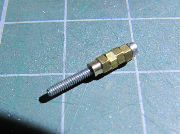

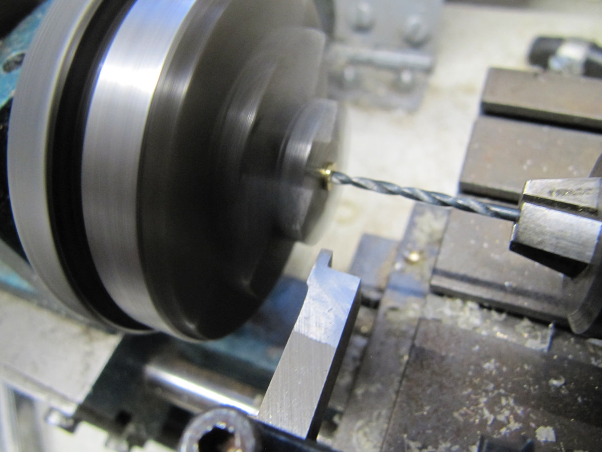
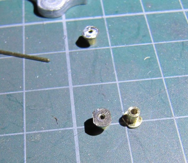

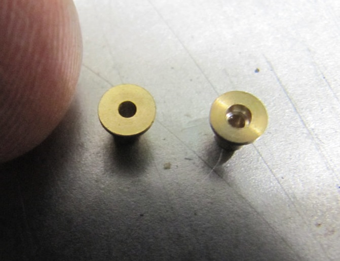
Take six 12BA nuts (you’ve got 6 cranks to do) and assemble them on a long 12BA screw. Put the assembled nuts and screw in a small drill, the threaded end being held in the chuck. While the drill is revolving, use a file to take the corners off the nuts until they are round and about the size of the screw head. Measure the diameter of the filed nuts so that you can stop when you get to the size of available drill – I used 2.1mm. Next put a Top Hat Bearing (THB) in your lathe. Drill into the THB to a depth not greater than a modified nut. Other methods of doing this are available. Put a modified nut into the hole in the THB. They were a tight fit and needed to coaxed in with a hammer. Check that a 12BA screw goes nicely through the assembly. Add a small bit of solder round the nut. I had an oiled 12BA screw in place so that solder did not go down the thread. A quick filing finished off the assembly.
A mixture of pins and 14BA screws was used to assemble the valve gear. Not too many pictures were taken here. One side was a learning curve and some of the rods had to be shortened due to replacement casting being used which were slightly larger than the supplied white metal ones. The right hand side valve gear was eventually assembled and worked well, again, without binding and without the coupling rods. The thinking was that if they work individually then they’d be ok when assembled. And yes they did, but that surprise came later.

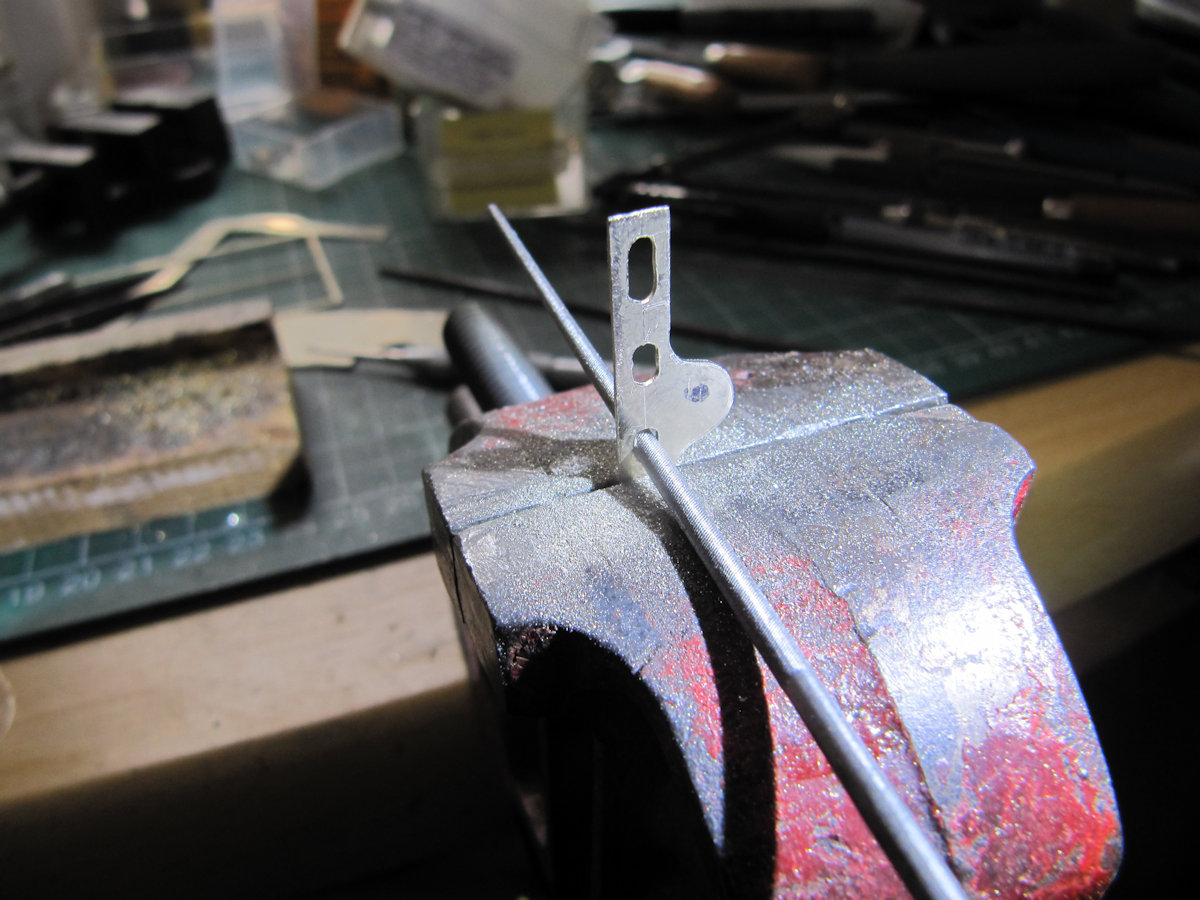
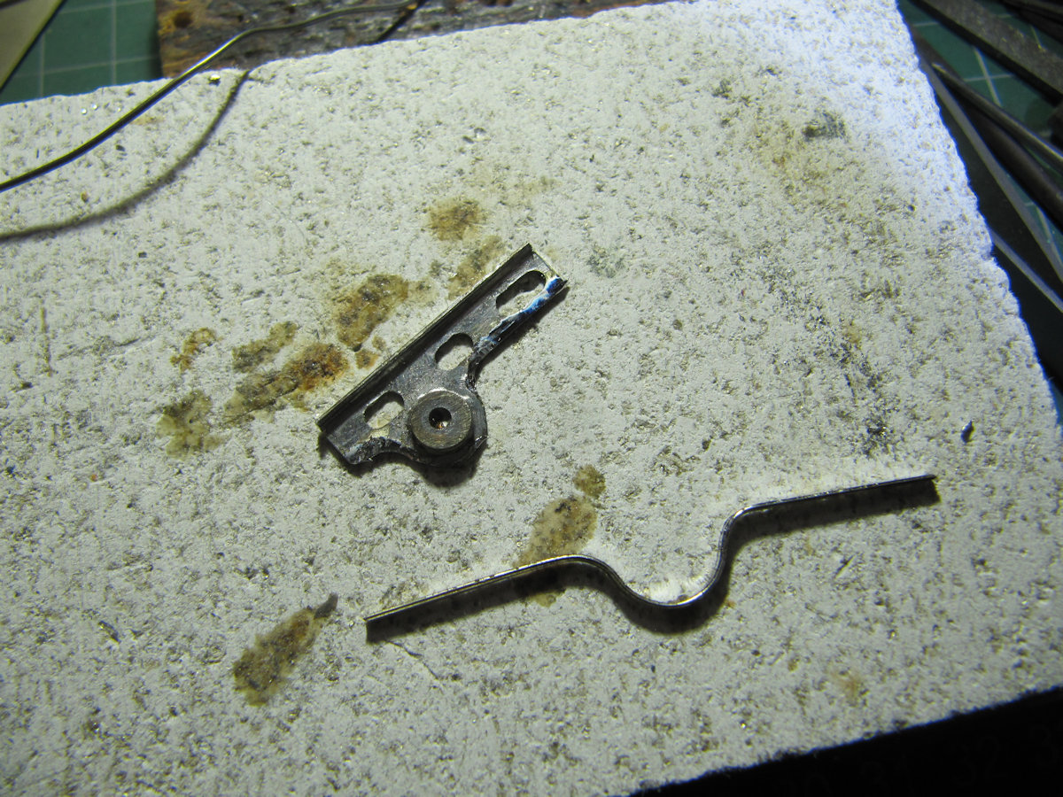
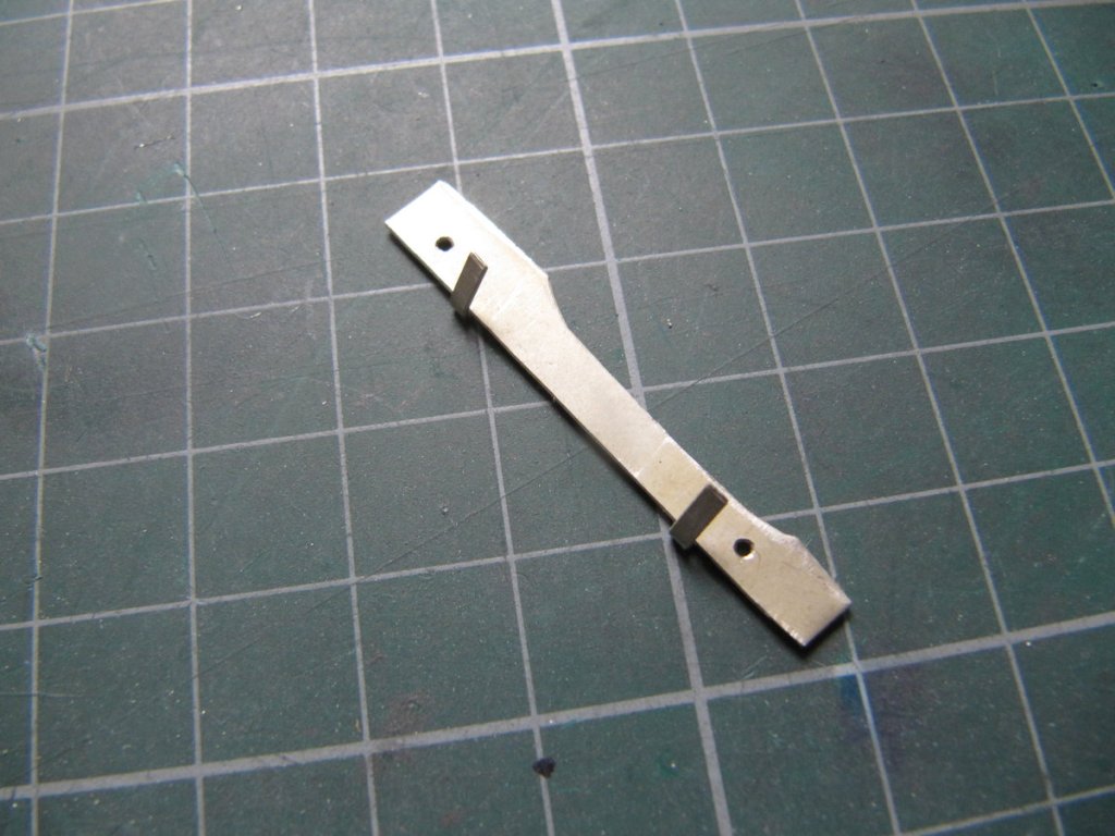
The expansion link trunnion castings needed modification on the inside to allow the link to rock. This trunnion casting was the one that was missing from the kit and supplied by Dave H from Bob A’s box of white metal castings. On modifying the casting for the left hand side, brain fade struck – I modified the wrong side! Could I make a recovery? In a word – no, so a fabricated one was made up from nickel silver sheet.
Once that was completed the final assembly of all the valve gear, con rods and coupling rods was done on both sides.
[Ed] – a video with a most unexpected soundtrack was circulated to members that proves the complete assembly to not only look good, but to be very free rolling!
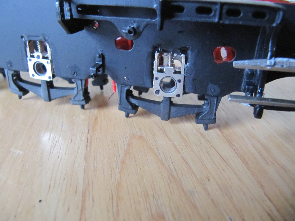
The chassis then had to be stripped to attach brake hangers and the 3D printed main springs.
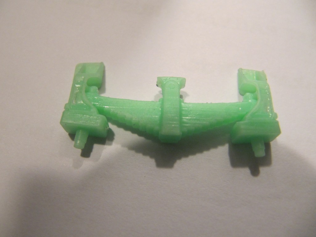
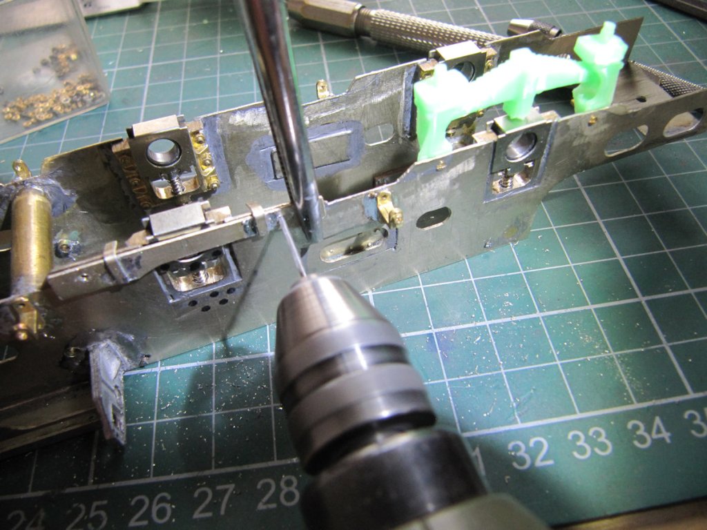
To attach the main springs to the chassis I used 12BA nuts and screws. A jig was made to drill the holes in the chassis in the right place.
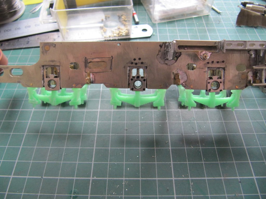
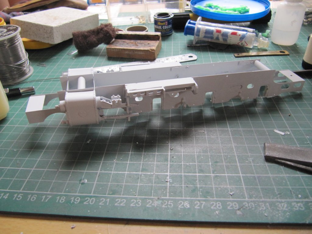
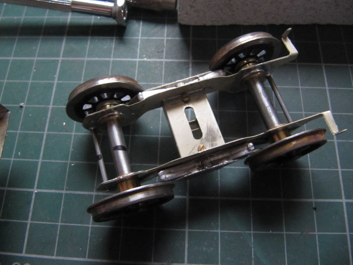
Once that was done it was time to consider where to attach the electrical pick-ups. Short lengths of copper clad were attached to the chassis to which the phosphor bronze wire would be soldered later on. Then it was time to give the chassis a coat of “photographic grey”.
Once that was out of the way it was time to make the front bogie. The lateral location was modified from that suggested by the kit instructions. I used a little something I learned from Bob A.
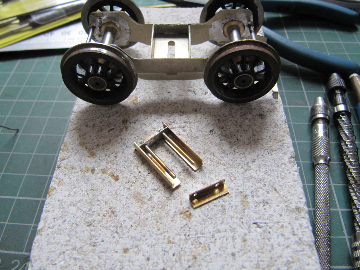


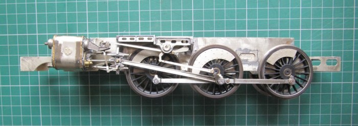
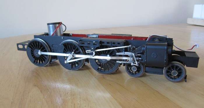
And the finished job:
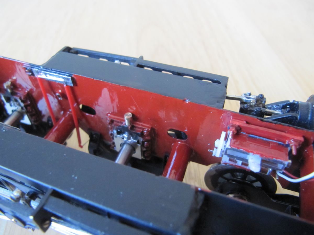
The motor was located with a wide omega loop attached to the chassis. The chassis was painted matt black and the inside red.
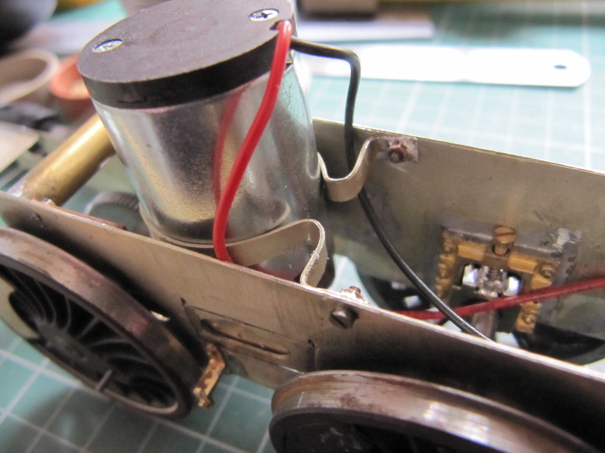
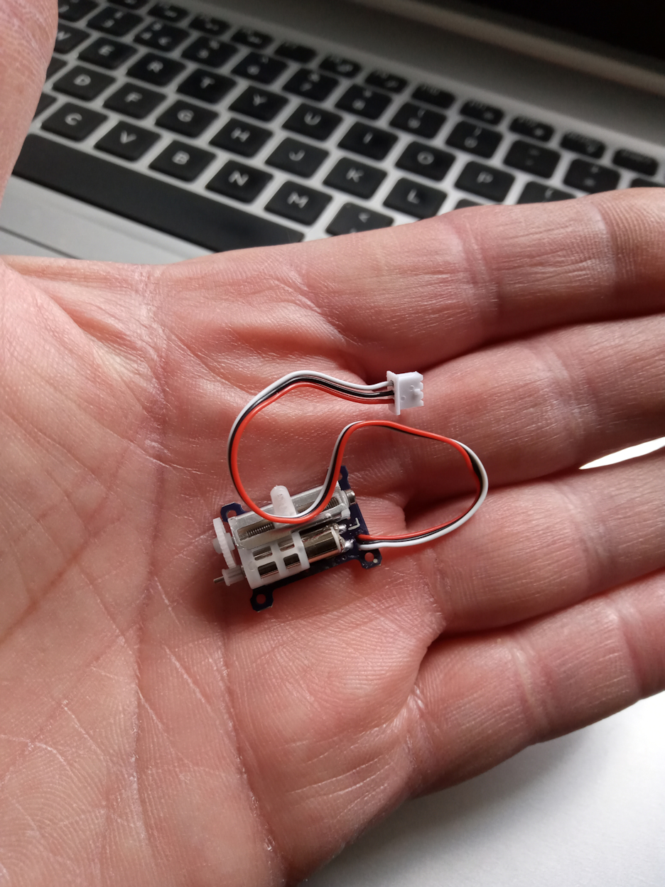
To enable the reversing gear to work a small linear servo was obtained. This was attached to the inside of the front of the chassis. Two of the pick-up wires can also be seen.
Then it was just a matter of putting the valve gear back on and trying it out on my yard of O gauge track with little low speed control from my Hornby Dublo controller. I would add a link to the video Dave made, but as is customary now the soundtrack is a little disturbing for Youtube. And yes, it does run as well as it looks!
Part 2 Covers the Loco body construction.
