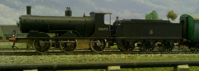
Verwood needs at least one Black Motor; and indeed they could be found on occasional passenger workings in addition to freight duties. This story starts at Taunton Rail-Ex in 2016 when I spotted a nice little 00 gauge Black Motor on Ray Heard’s stand. Although of indeterminate origin it captured the look of a working loco so nearly enough money to buy the then recently released Hornby model changed hands and it was mine! The model purports to be 30692 and this engine was indeed photographed at Wimborne with a goods off the Fordingbridge line!
The model is brass and where there is riveting it is very regular leading me to think that this is an etched brass kit rather than scratchbuilt, so perhaps a Jidenco? The crew were posed with fireman on the tender with hand on brake and the driver sitting on one of the splasher/toolboxes at the side of the cab; I have a strong feeling that this cameo reproduced something the builder had seen in life. The top of the chimney was light grey, which I haven’t seen on any other models, but reminded me of the colour of the exhaust on my old Ford Anglia after a long run. The 00 gauge underpinnings were distinctly undercooked, but that was fine as I envisaged replacement Perseverance chassis for engine and tender.
I’m still grappling with the EM gauge conversion of the super fragile Hornby T9 with tiny plastic parts breaking left, right and centre and only room for the wheels under the splashers after major surgery. Given the potential for similar problems with the Hornby Black Motor; how dear readers could the conversion of this unusual and robust etched brass model not be a quick win in comparison? Incidentally for those with a Hornby T9, is that fragile plastic lamp iron on the top of the tender still there? Do you still have all of the fragile plastic handrails round the cab, and the whistle?
Tender
Already having a 7’+7′ Perseverance tender chassis kit in stock, I built it up using twin beam compensation with High Level mini-hornblocks with some mods to the frame profile to better match the outside frames. Here we hit the first ‘opportunity’ in that the generic brake blocks provided were the wrong shape so a suitably chunky set was fretted out from N/S sheet, built up and fitted.


I also made provision for my favoured Kadee coupling at the rear using a #26 or similar to give me a longer shank. The wheels were ancient Romford mazak items with heavy flanges so they were turned down and generally cleaned up in a hand drill with files to something closer to current EM standards. The result was a smooth running tender – now for the engine.
Engine
The engine came with a Mashima open frame 1019 motor. On the face of it this seemed a reasonable option so this was paired with a new 53:1 Branchlines Multi-Box driving the centre axle with the motor vertically mounted in the firebox. So far so good. My favoured compensation system is twin beam, and with the rear two axles linked this placed the gearbox where the pivot for the twin beams would naturally lie. Looking back I think it would have been so much easier to have put the twin beams on the front two axles! Anyway High Level hornblocks were duly fitted to some Perseverance loco chassis frames ‘borrowed’ from a Westward Black Motor kit, and the twin beams were cunningly pivoted on the threads of 10BA studs which just left enough room for the gearbox to slide from side to side between them (a requirement for centre drive). The engine also came with Romford wheels and I thought it would be a nice touch to retain those (a quick win remember), so I invested in a set of deluxe crankpins and some EM axles to fit the wheels on. As with the tender the wheels were carefully refined on my trusty hand drill using files and fitted to the chassis. Pickups were also arranged using P/B wire on double sided PCB on the insulated side and the body test fitted to the working chassis.
At this point the more perceptive of you will have realised that a) Romford wheels are over scale thickness, b) the throw on a Romford wheel is rather greater than the scale 9″ favoured by the LSWR, and c) that the coupling rods would therefore strike the very narrow running plate of a Black Motor leading to a very lumpy test run. What to do? Unusually a finescale wheel of the correct pattern is not currently available for the Black Motor from any source, although Alan Gibson do a close match albeit with the wrong throw. This wheel has a dimple where the crankpin belongs so there is scope for drilling the crank in the right place, but it seemed to me that this approach would work even better on the metal wheels that I already had, so I epoxied some 10BA brass threaded rod in the existing crankpin holes and made a jig to drill the holes in the correct place (or at least the same place) on each wheel.

The drilling was done on my Record Power drill stand, whilst the tap was hand turned in my Expo drill and stand to ensure that the 10BA tap was vertical. The finishing touch for the wheels was to cut the distinctive balancing weights from ABS and to glue them in. I even filled the space between the spokes behind the weights with epoxy putty, but that’s just me.

With all that sorted out it soon became obvious that the M1019 was not going to be man enough for a punchy little goods engine that was a close relative of the famous T9 class. Since Mashima motors have gone out of production I tried a Mitsui motor. The first motor was really slow and couldn’t reliably spin the wheels with the etched brass body mounted. After much ‘discussion’ with the supplier this motor was returned and found to have misaligned bearings. The replacement motor was very torquey but incapable of a decent canter when mated to a 53:1 gearbox, so I caved and invested in a Mashima 1420 from the final production run (with a third 53:1 gearbox etch) and that works extremely well and gives a reasonable top speed.
-
Test run with revised crank pins, but engine and tender sitting a little too high.
I now had a working chassis, but no injectors, brake gear or sandpipes. Whilst the tender chassis is generic the loco chassis is specifically for a Black Motor, so it was disappointing to find that the brake blocks were too spindly to represent the chunky prototype blocks, so once again the brake gear was drawn up (from the Bradley drawings), printed

out, glued to some nickel silver sheet and fretted out. This (like the tender brake gear) I found surprisingly satisfying although I find it now needs my most powerful reading glasses (+3.0) to accurately follow the line. I cut seven sets of parts to make six as I knew that at least one would go missing and I was not disappointed! As with the tender the effect is definitely worth it. The injectors were a copy of the plastic moulded ones supplied with the Hornby T9, fabricated out of wire and bits of brass hypodermic tubing and mounted on an angled plate that simply hooks onto the frames. Similarly the sandpipes (front only) were fabricated from wire and fitted in holes in the chassis.


Finished chassis and gearbox prior to re-assembly after painting
Prior to painting the engine had run faultlessly through my test point, after painting and re-assembly it could not be induced to do so. After an hour of mainly checking for adequate side play in the chassis, I ran a track gauge over the ancient plastic welded pointwork and found that the closure rail had moved tightening the gauge. There is a moral there somewhere!
The footplate of the cab was judged to be too low but a layer of code 4 lead corrected that and added some useful weight. The fall plate (cut and formed from a Shedmaster etch) was attached to the tender as this better suited the cab layout, and was essential for a fixed fall plate given that the drawbar was mounted on the engine. The drawbar being an EMGS item donated by a fellow YMRGer. The final touch was a beefier chimney turned up by another member on his lathe, to which I applied that light grey top that the original had. So that’s at least two more benefits of joining YMRG – thanks guys!

The completed Black Motor fresh out of works hauling an excursion on South Junction with one of those very nice Hornby ex-LSWR non-corridor coaches in tow.
Footnote: Actually on studying the photos closely I now remember that the cast white metal brake pipe fell off the tender which is also lacking any lamp irons. Replacement scale lamp irons are also on order for the front. Then there’s some weathering to do, and the brass Markits nuts on wheels and coupling rods to blacken. A modellers work is never done!
The Ends – a postscript
As noted above there were a few cosmetic snags that needed attention greatest of which was the lamp irons for front and rear. The missing smokebox irons were created by using a GW rivet press to put three rivets close together in a line on a piece of .010″ nickel silver and to drill out the middle one 0.5 mm drillbit to hold a pin. Two of these pieces were soldered together using brass rod to line them up and then the T+L shape was fretted out and refined with a file. Once unsoldered brass wire was soldered in to each one and they were the bent to shape and glued in position. The rear irons were also fretted out centred on a predrilled hole leaving a square shape round the hole. as per the prototype. The plan was to use functional white disks, but the ones I fitted with brackets proved too large at 5.5mm to look right on such a small smokebox, and alternatives that do look the right size have been sourced from Roxey Mouldings.
Also missing was the two little boxes on each side of the firebox so these were made up from 1/32″ brass, painted and glued in position. Lastly a rear vacuum pipe has been fitted, and although a little overscale is normally out of sight so I think will do.
Not cosmetic was the large 4′ tender wheels rubbing the bottom of the tank and eventually removing the paint and causing fairly frequent shorts. The solution for this was to use a plastic jig to accurately drill holes at each end of the required slots and to join the holes with a diamond disc in a mini drill. The resulting slots were tidied up with files and the necessary clearance achieved.
