The Locomotive Body
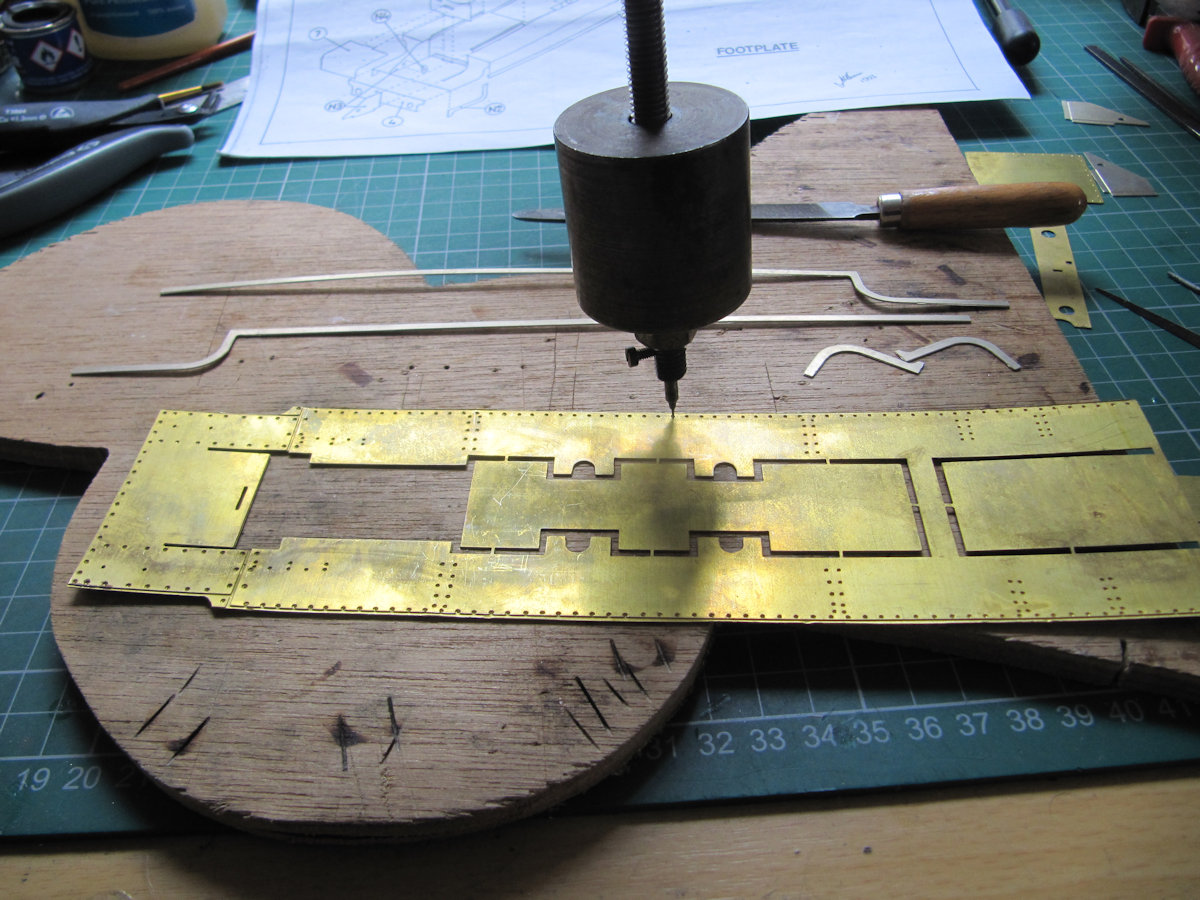
Having achieved a smooth running and painted chassis in Part 1. Dave S moved onto the body. The first thing to do is punch all the rivets (in the right places of course). The footplate is first. I’m using the tool Bob A used to use. It’s just a heavy weight and point. It sometimes goes through the sheet and you have to hammer the head back into position. Care is needed. You end up with neat rows of “bumps” on the other side. Most kit manufacturers put dimples on the reverse side as a guide to where to punch the rivet head. With the rivets punched, the footplate could be bent to shape, the edges attached and a “clip” soldered to the back of the buffer beam. This allows the front of the chassis to slide between the two flat bits of metal and locate the front of the body on the chassis. There is an 8BA screw holding it on at the back.


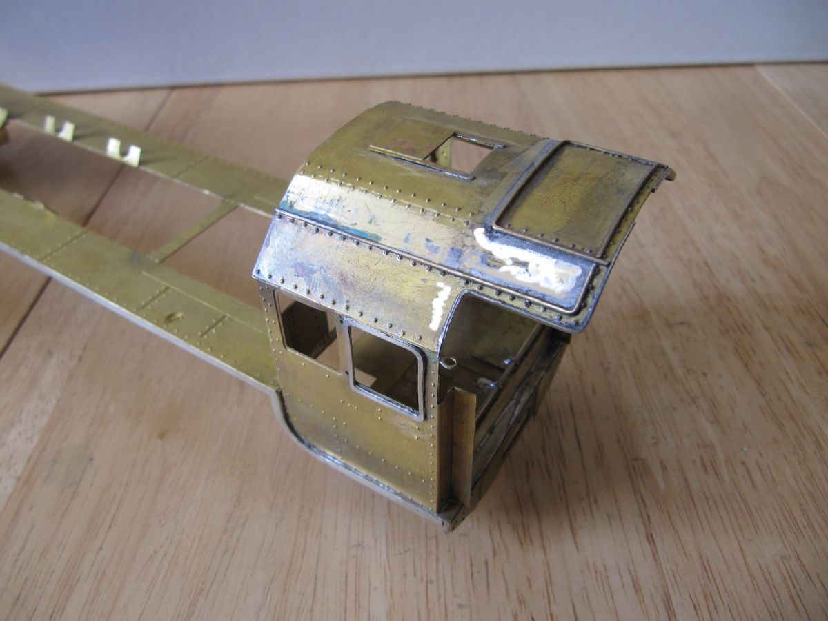
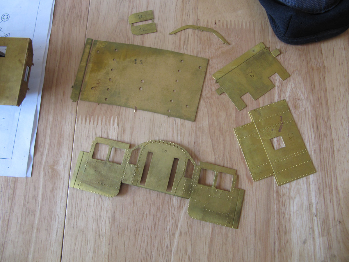
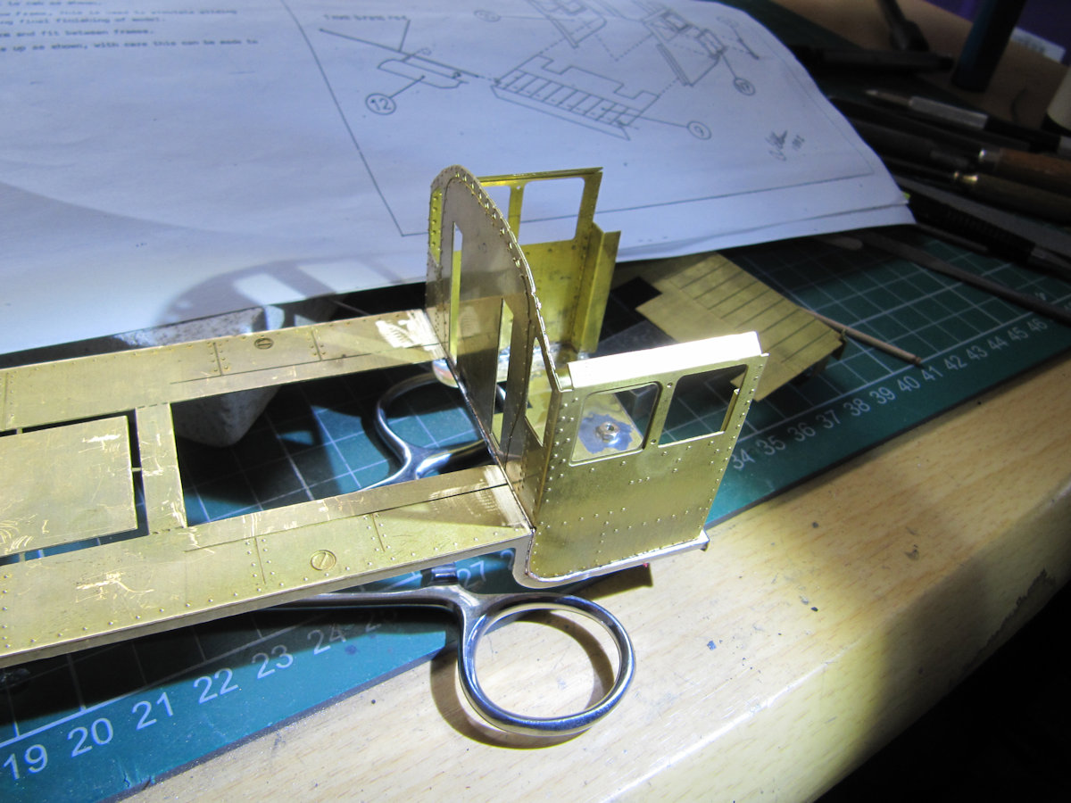
The cab is the first part to put on the footplate in this kit. Similarly to before, the rivets were punched before assembly. It’s a pity that the whole loco was not of welded construction! Assembly was reasonably straight forward.
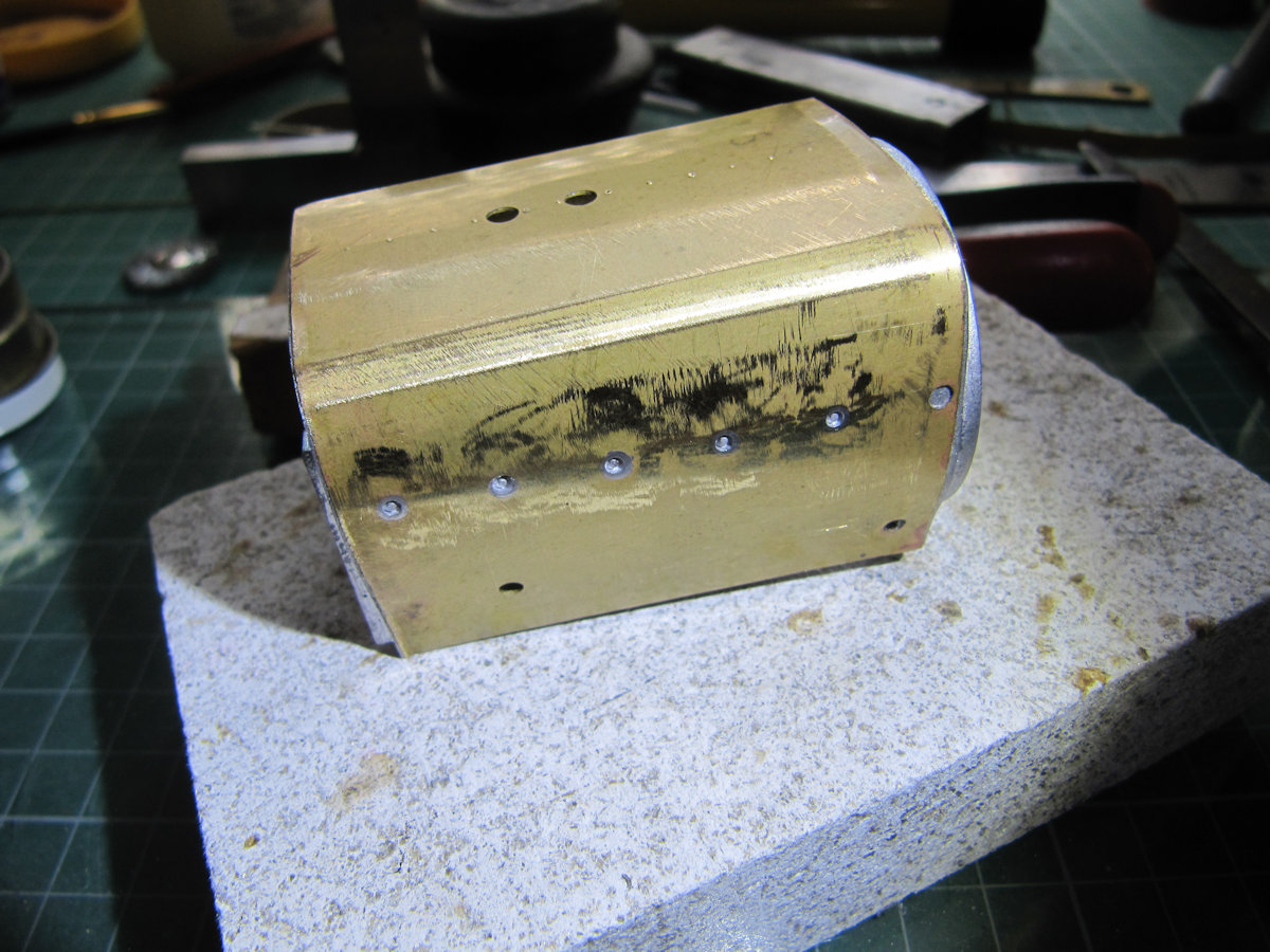
Moving onto the firebox, I now have to solder the brass wrapper to the two white metal ends. First thing to do is bend the wrapper carefully (after cutting it to the correct length for my model) using appropriate round bar and the white metal ends to get the shape right.Once happy with the shape, I followed the advice given in the kit’s instructions – tin the brass with ordinary solder then, using low melt solder, attach the white metal casting. After tinning, I applied flux to the tinned brass and the white metal part. I cut a small piece of low melt solder and placed it by the joint between the brass and the white metal item – starting in the middle of the joint. Applying quite a hot soldering iron on the brass near to the white metal casting, you can see the small piece of white metal melt into the joint. Remove soldering iron as soon as this has happened. You don’t want a pool of irreplaceable white metal casting on your work bench. After letting it cool for a bit, I work my way round one edge, from the middle, using a similar soldering method and keeping the wrapper tight to the casting with the aid of a heatproof glove. Again, after cooling, the other side was done. With one end complete, the other end was done using a similar method. Please note that other methods of attaching brass and white metal together are available. With the two ends attached to the wrapper, it was just a matter of soldering all the white metal casting and straps to the firebox to finish it off.

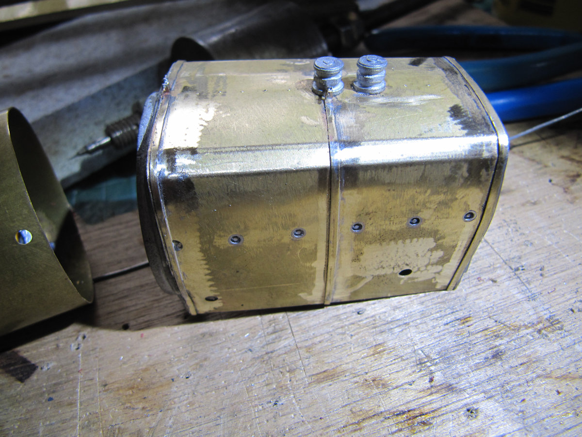
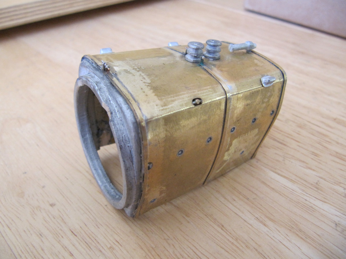
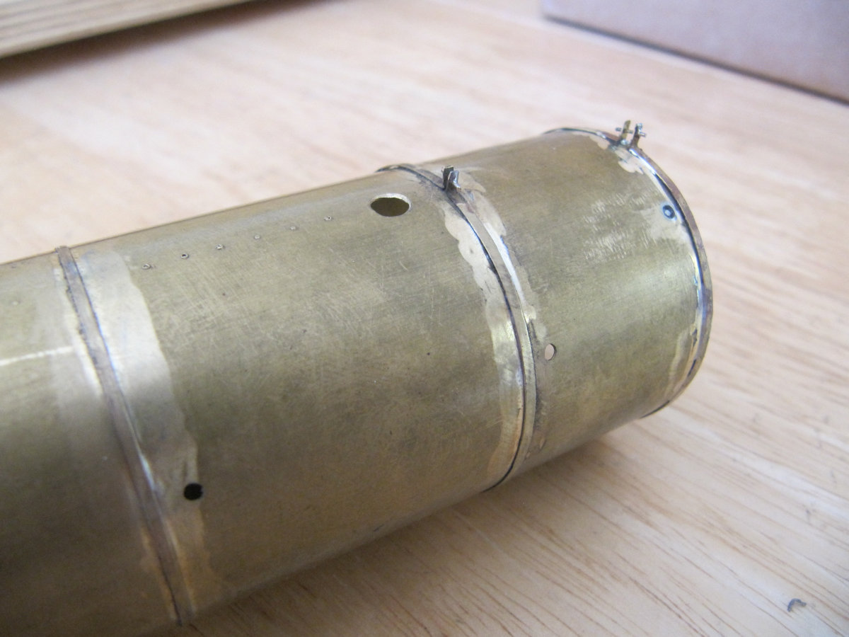
Next the boiler. This was already formed to shape and just needed soldering together along the joint. Similarly the smoke box. Ensuring the boiler and smokebox were correctly aligned, they were soldered together using an internal brass sleeve. Once that was done, again, it was just a matter of soldering all the white metal casting and straps to the boiler to finish it off.
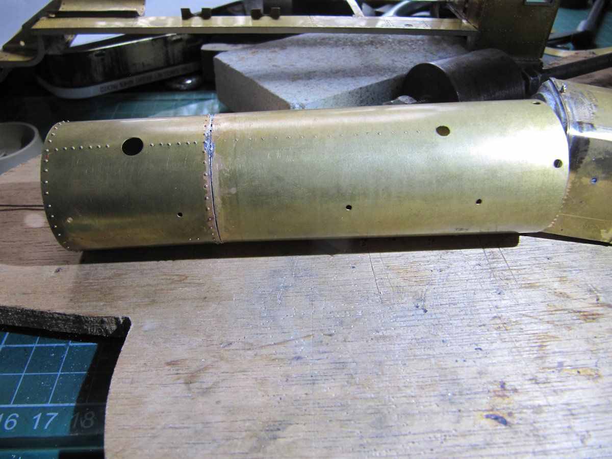
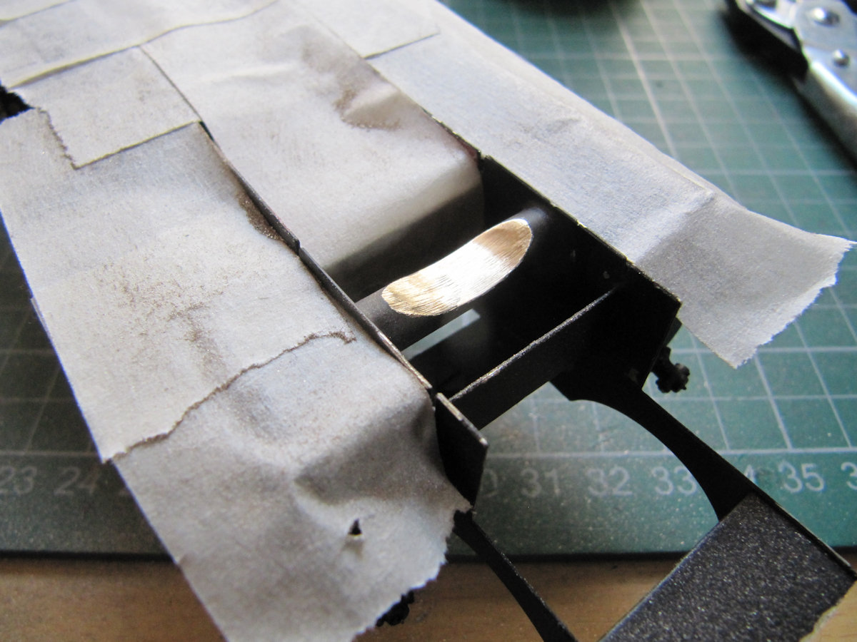
Now that we have the firebox, boiler and smokebox finished, a trial fit could be made of the body on the chassis. Modification of the front of the chassis was needed (as per instructions) to enable the smoke box to sit correctly. Metal was needed to be removed from the front chassis round cross member. Masking tape helped protect the chassis from the bits of brass swarf. With that done, the body sat nicely on the chassis.

Before continuing further we need to sort out a DCC sound chip for the loco. The chip will need to be able to work the servo for the forward/reverse mechanism from a function key.
To be continued…
