By Bob Alderman December 2010
Part 1 can be found here.
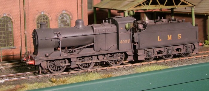
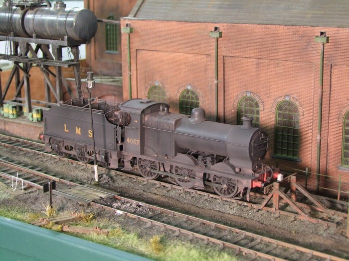
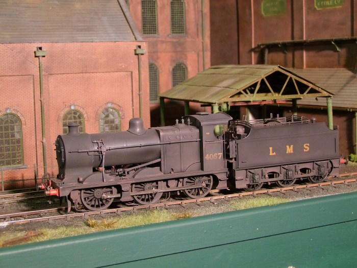
The loco is completed. Some cleaning up still required and final painting.


The new reverser reach rod. In reality this emerges from inside the firebox cladding. A small groove was made in the front of the firebox with a hole for a spigot on the reverser to locate in.

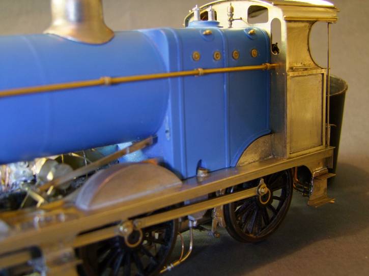

The lubricators have an imprecise location not aided by a slot in the footplate. My interpretation of the mounting brackets is that they are mounted with the vertical soldered to the outside of the frame and the horizontal inwards. This is born out by photos and the rivet detail (lost in the picture) being on the outside.
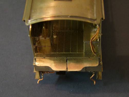

The fall plate provided is a one piece chequer plate item. It does not match photographic evidence that it was plain and divided into two. The outer cut-outs are to clear the brake and water scoop columns on the tender.
I fitted small loops for the fallplate at the back of the cab floor wit h lugs on the plate.


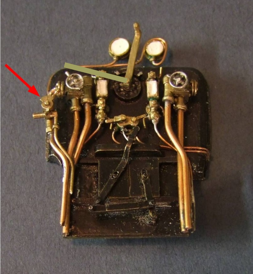
The backhead seems somewhat cramped. The sanding jet in the middle seems a little large as it interferes with the gauge glass cocks. The regulator lever is not correct it needs a second arm, drawn in on the picture. Yet to be changed. I added a Laurie Griffin Midland combined steam/vacuum brake valve – arrowed.

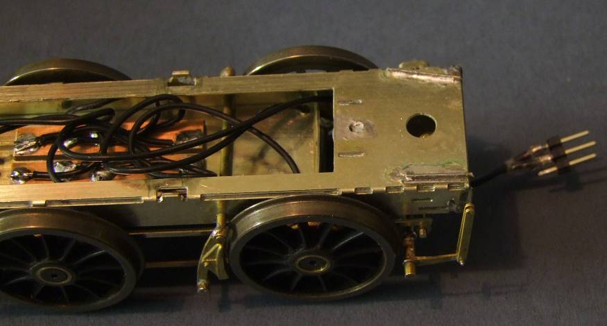
There is no provision for a drawbar in the kit but a hook and loop, as I wanted a more permanent connection I made one shown below. This required a screw on the loco, arrowed, to locate it.
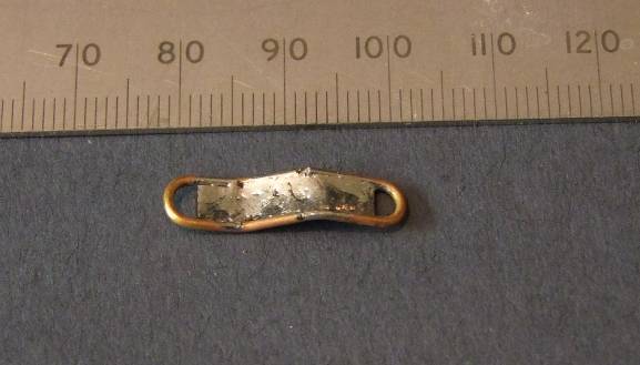
It is kinked as the slots in the tender and loco are different heights.
The drawbar fits above the frame spacer when the body is assembled. The nut inside the slot seems to be superfluous. I removed it and opened up the slot (not well!) to allow the drawbar more movement.
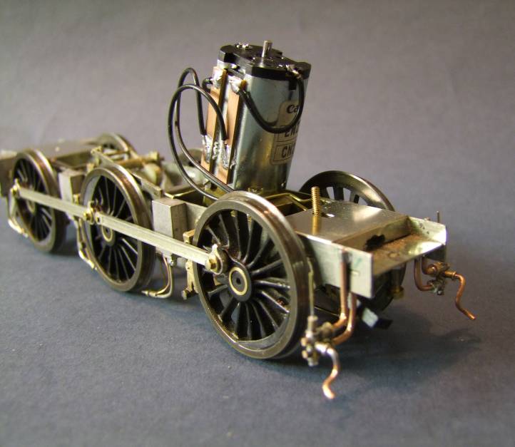
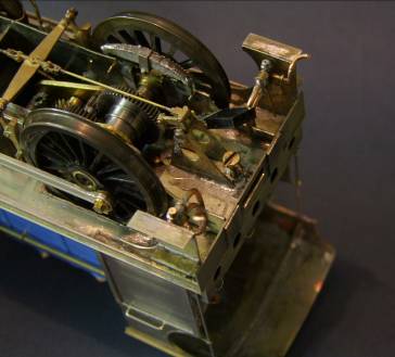
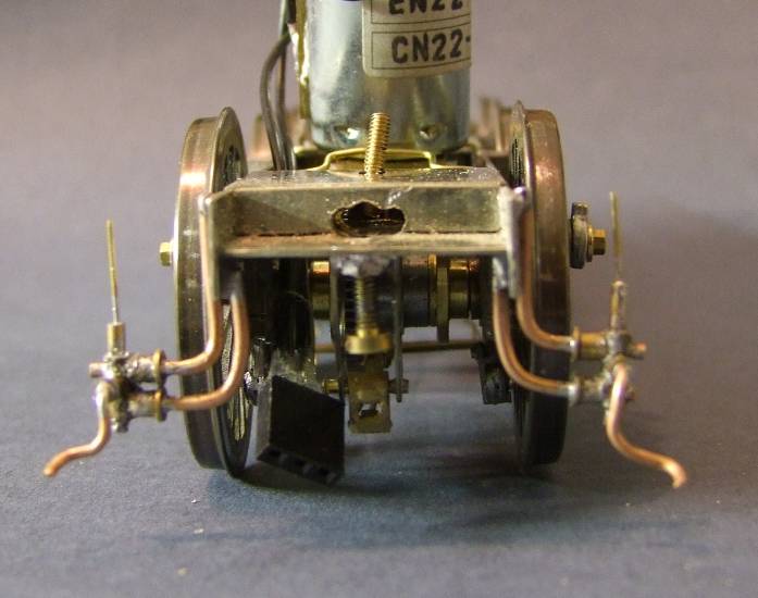
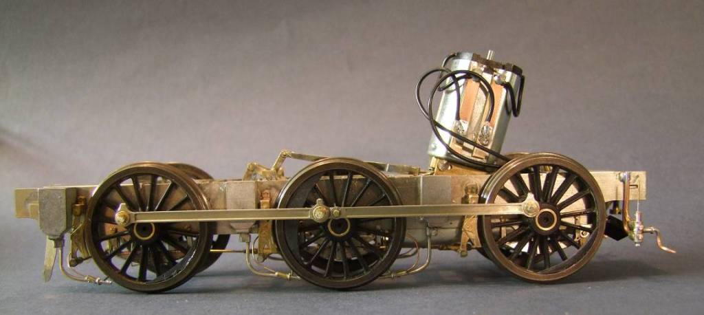
The completed chassis with scratchbuilt injectors fitted. The ones supplied are too long. These are “sketched” in brass tube and copper wire. The overflow on the off side has been bent out of plane.

They sit behind the cab steps so I feel that total accuracy is not needed but hey need to be seen there.
Sanding pipes added to the sandboxes.
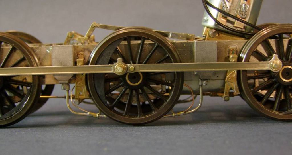
Note the sand pipe is not directly fixed into the box. There is an offset trap, represented here by a small diameter brass tube on the end of the pipe.
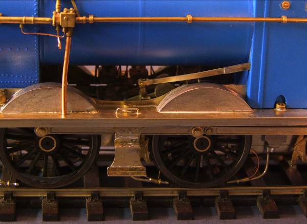
Note the addition of plasticard balance weights, not provided, to the wheels.

The steam pipe is fitted into a shaped brass tube. Brass wire supports are also fitted. These, on both model and prototype, stabilise the end of the pipe. The brake shoes arrowed needed material removed inside the show to prevent contact with wheel.

The tender completed. Note the internal braces. I’m not convinced the front ones are in the correct position but this is where they best fitted.
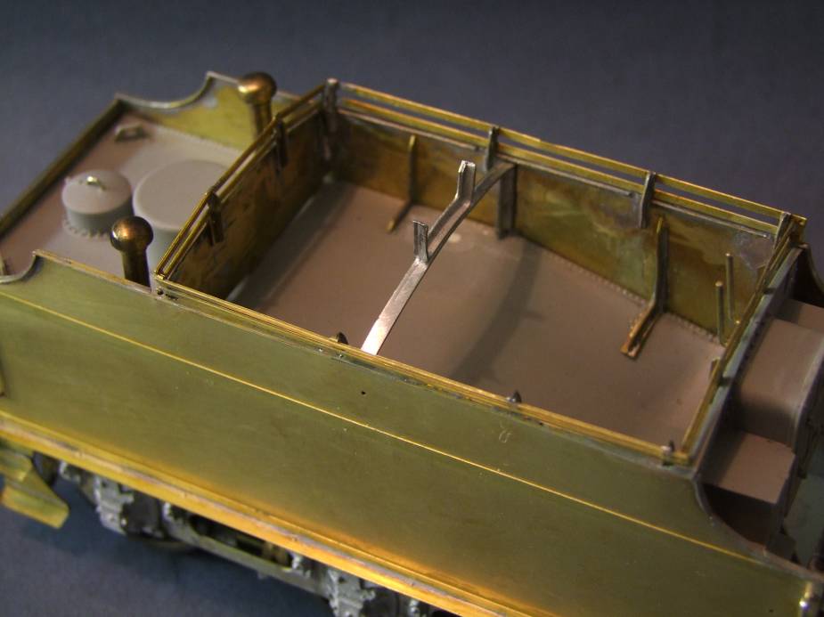
As built the tender sits low relative to the loco, this can be seen by the alignment of the footplate and steps. To correct this I soldered on four lengths of 0.7 mm wire at each corner of the sub chassis. This lifts the tank assembly.
The finished engine posed in an appropriately industrial setting on the club’s Gas Works layout.