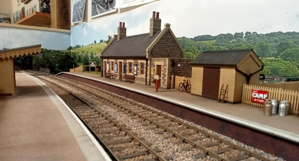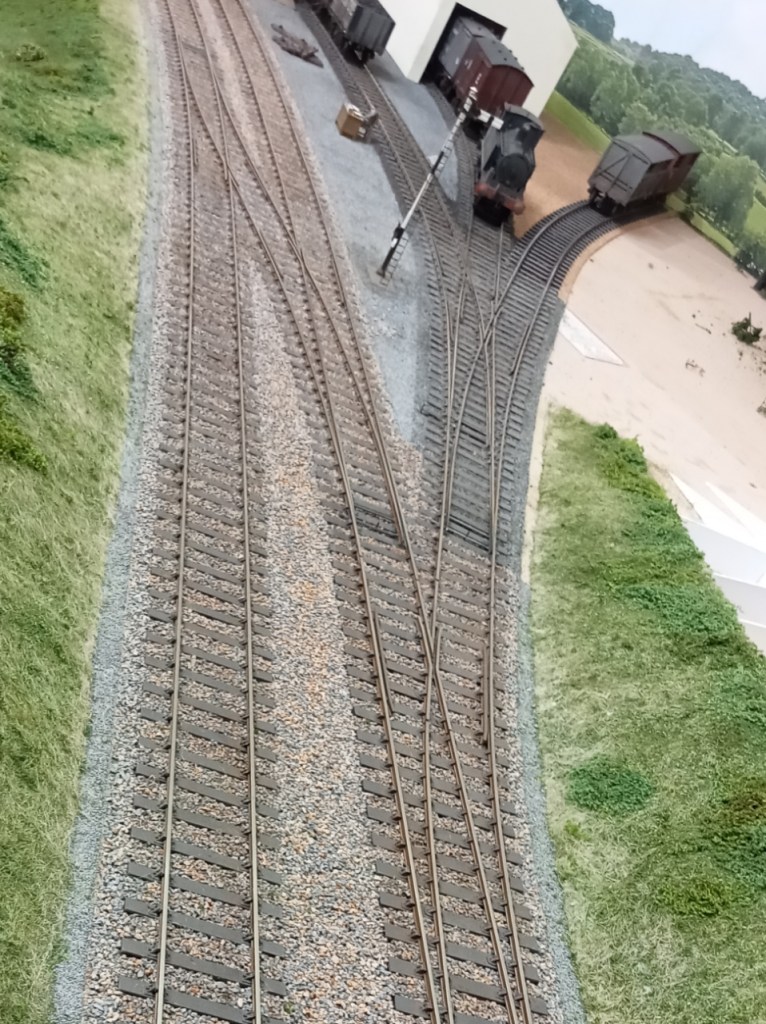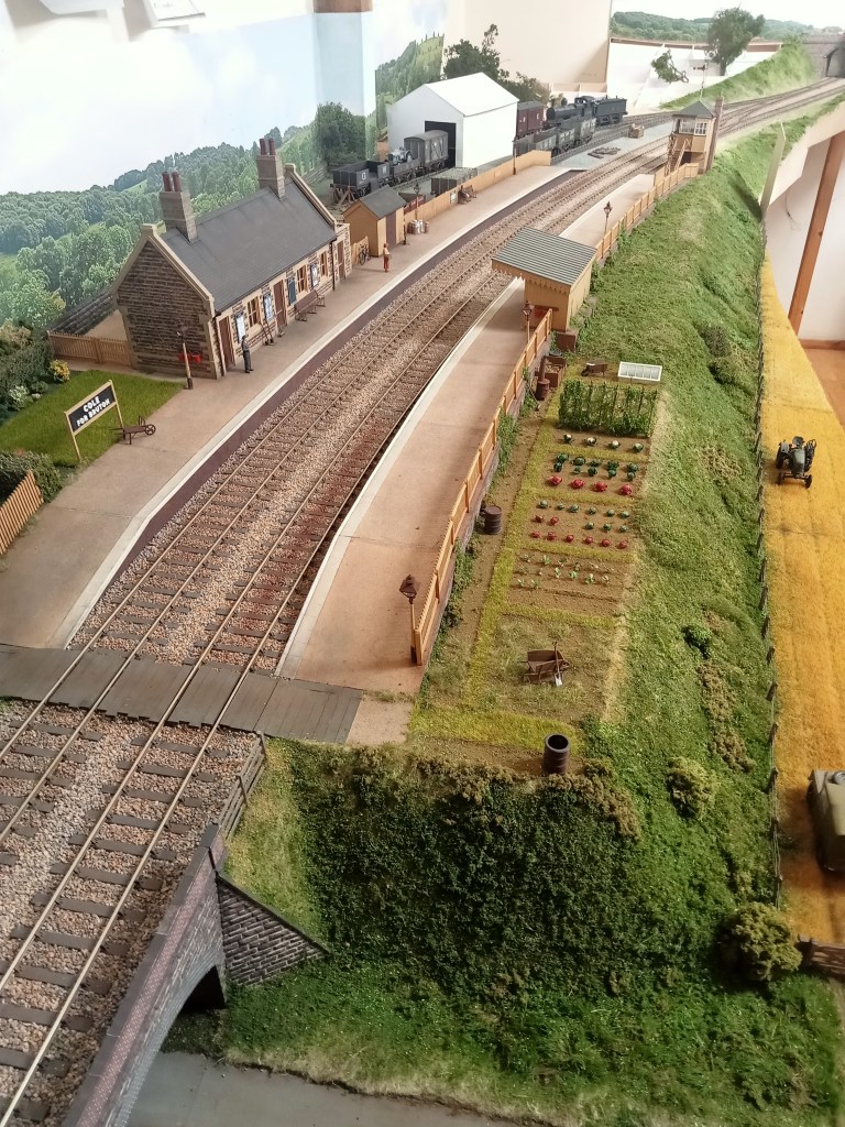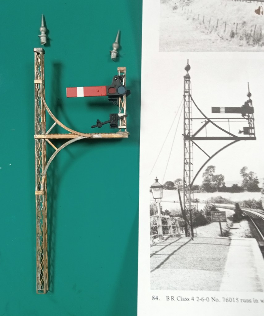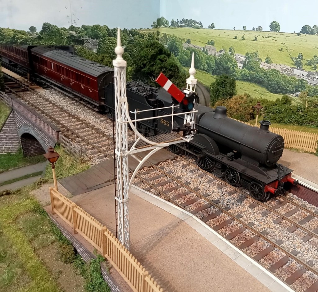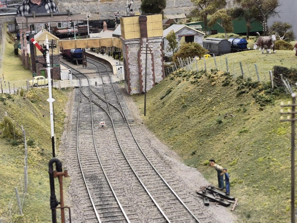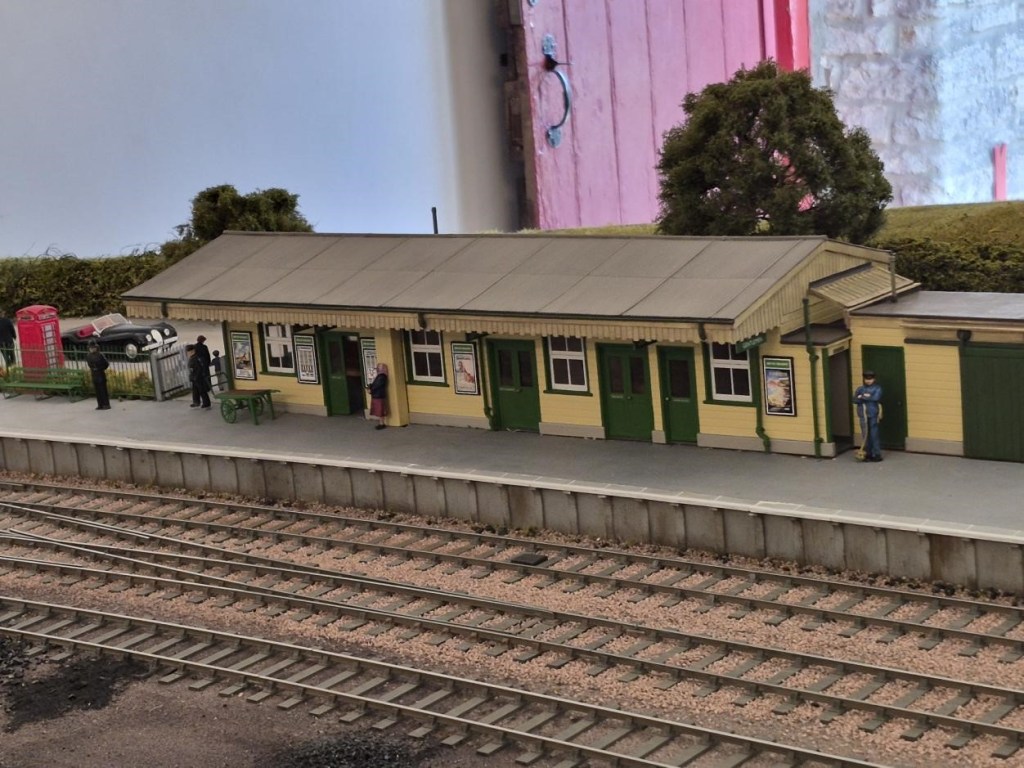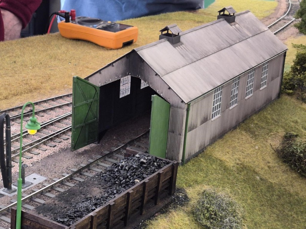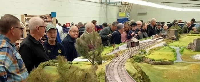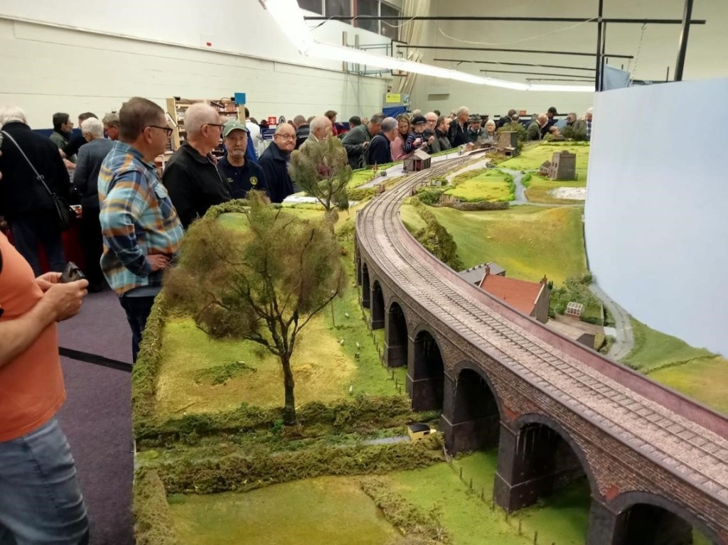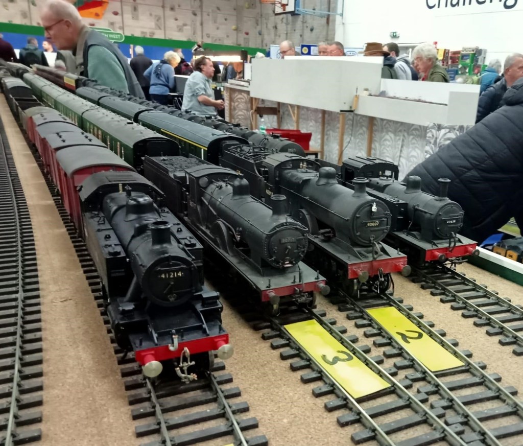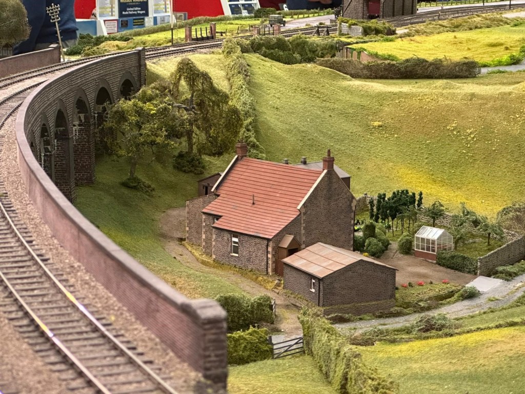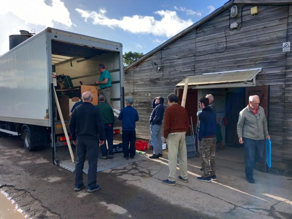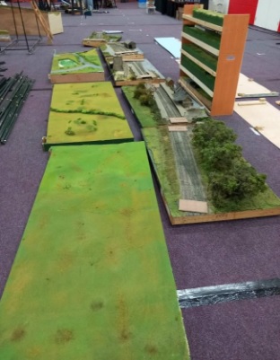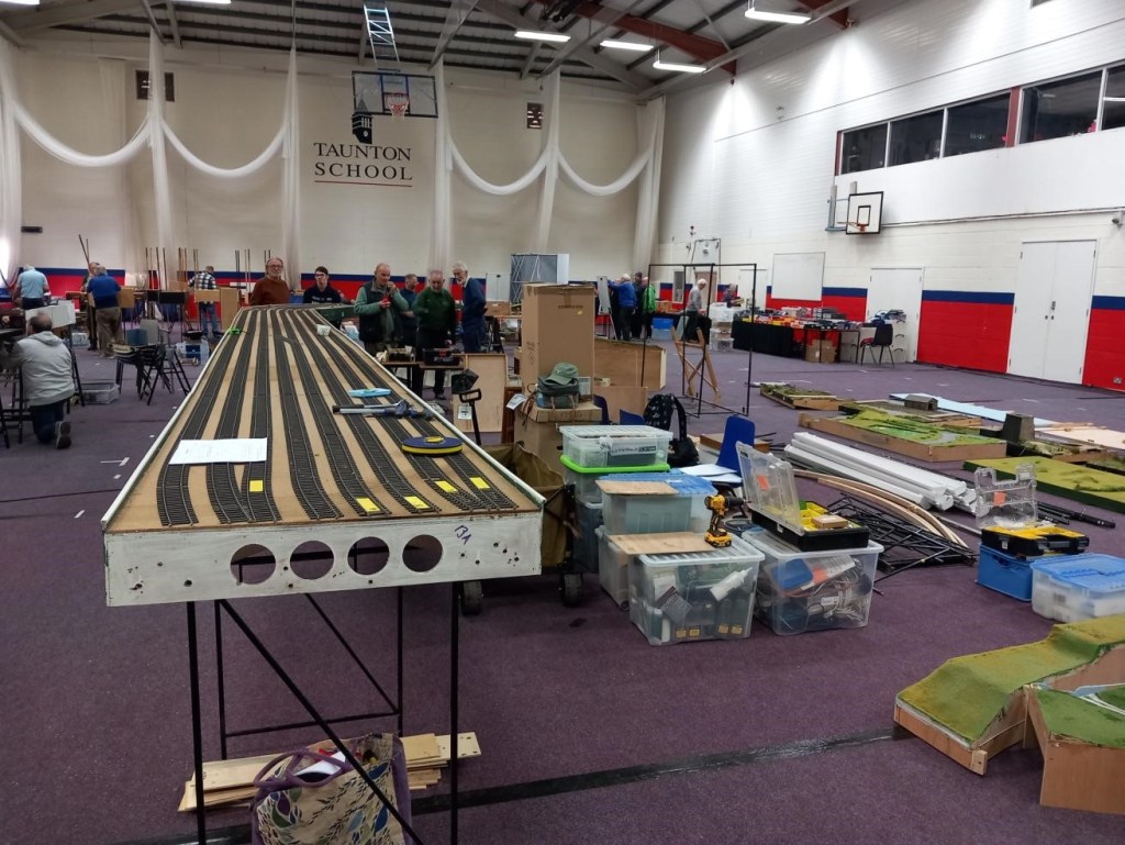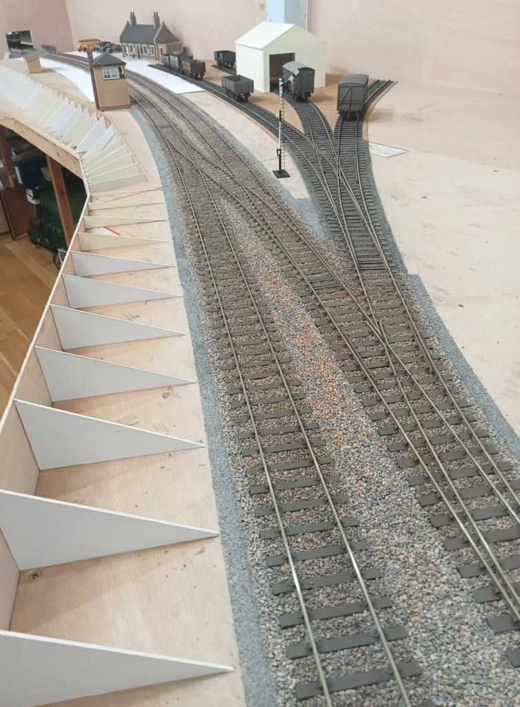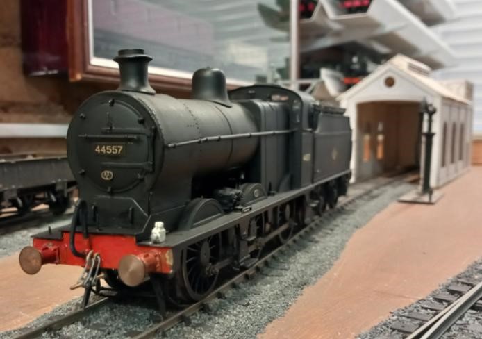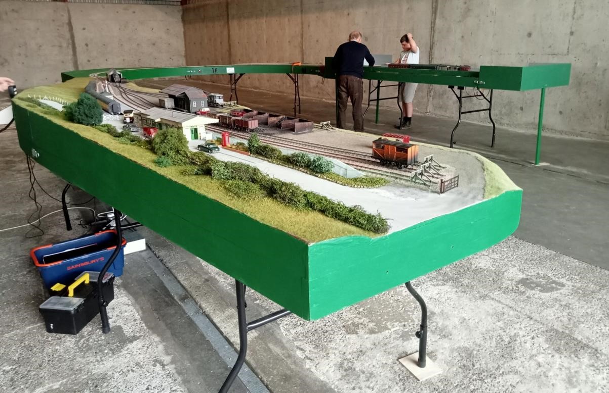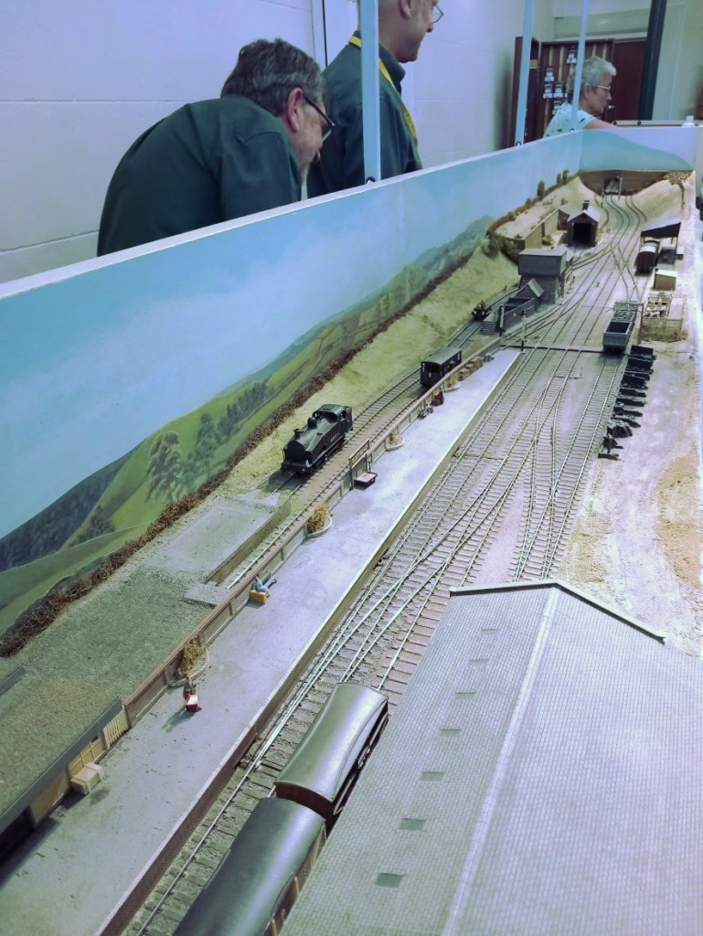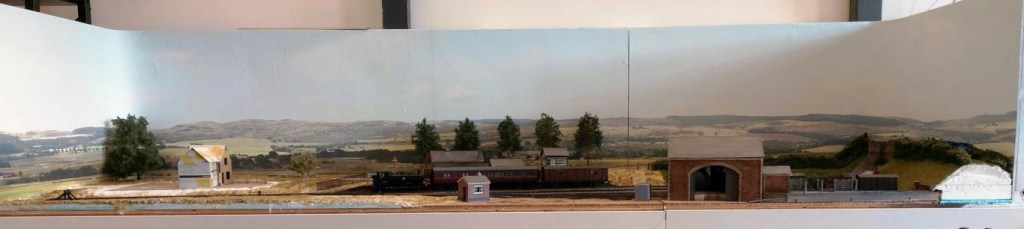
David’s Open Day in April featured both Nethercreech Junction and his new creation Lyme Regis. Some photos taken by YMRG members of Nethercreech Junction follow:
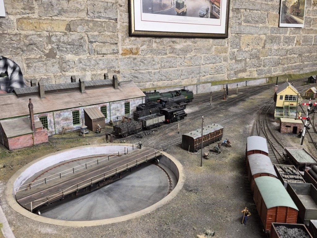
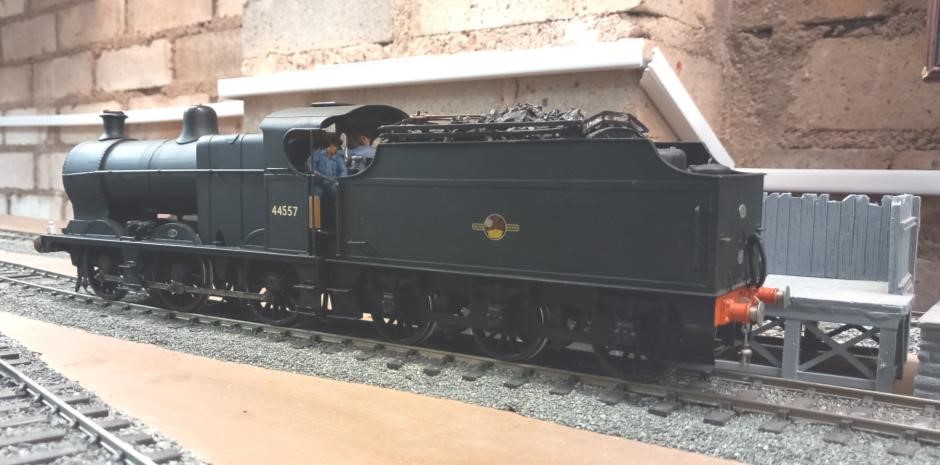
NetherCreech Junction Loco Depot
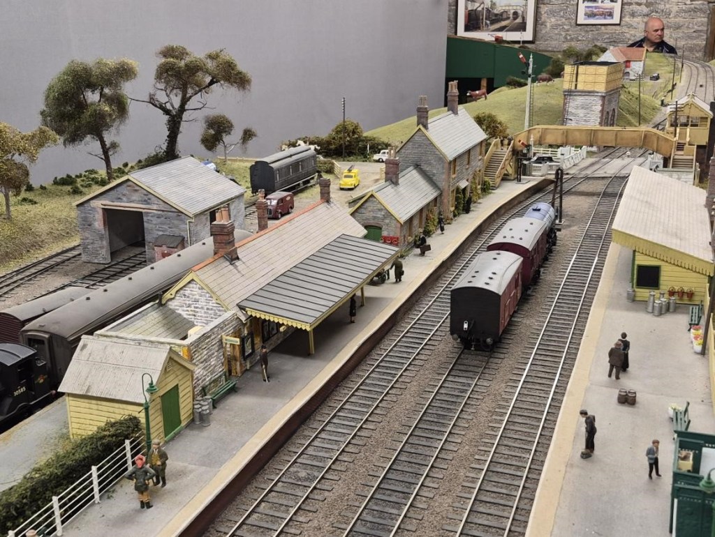
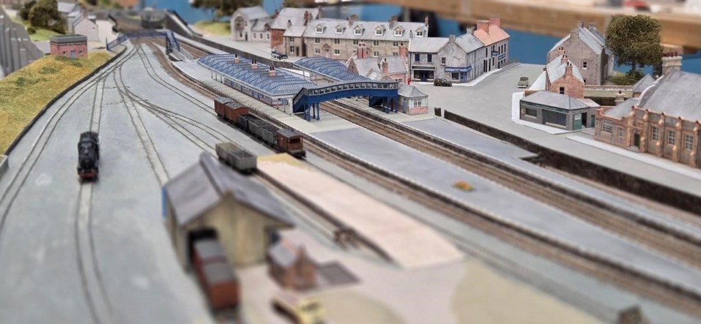
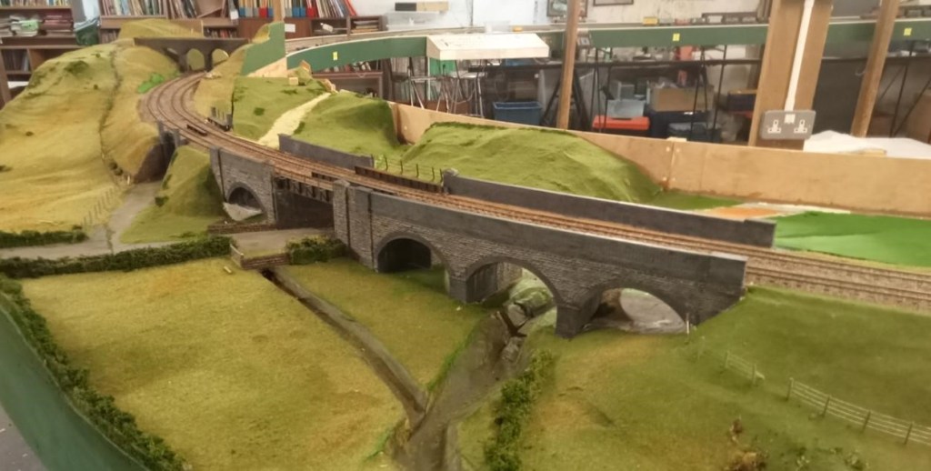
NetherCreech Junction Looking South
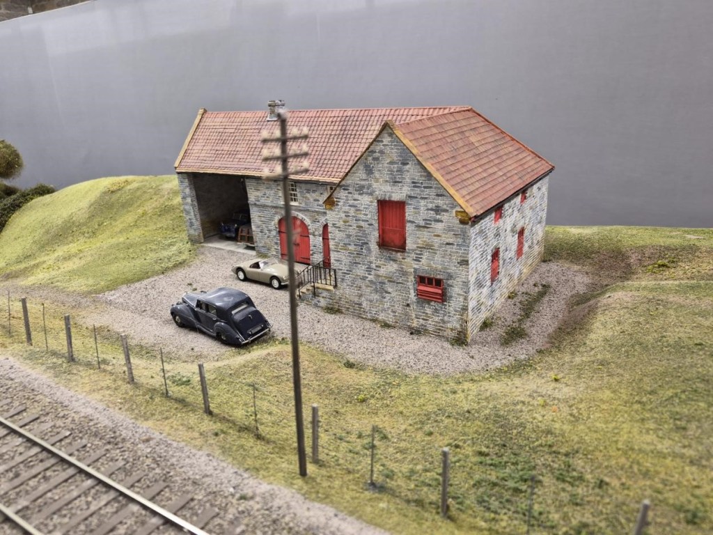
A Model of the Barn that Houses Nethercreech Junction and Lyme Regis painted in Estate Colours with Ivo Peters’ Bentley outside – as it really was on the Open Day!
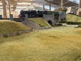
Looking North towards the Level Crossing
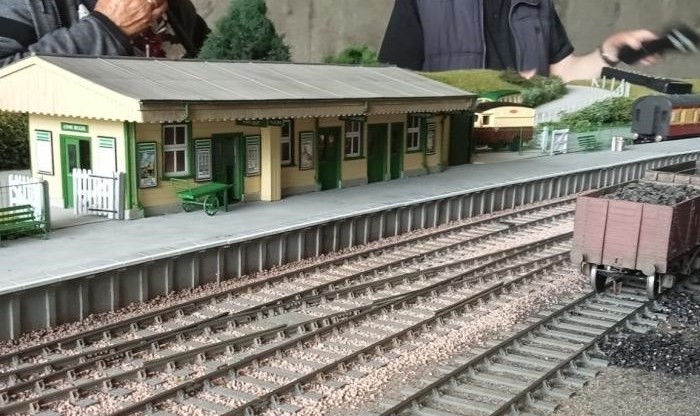
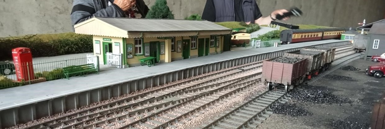
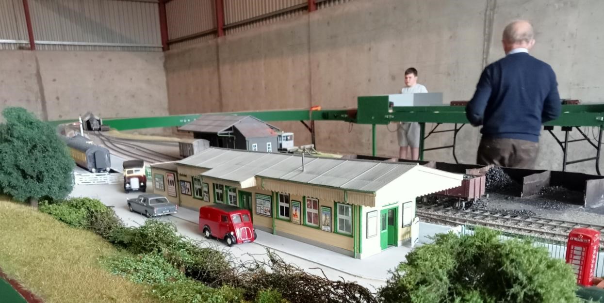
And now two views of Lyme Regis. Member and retired architect Allan has been responsible for the buildings and excellent renditions they are too:
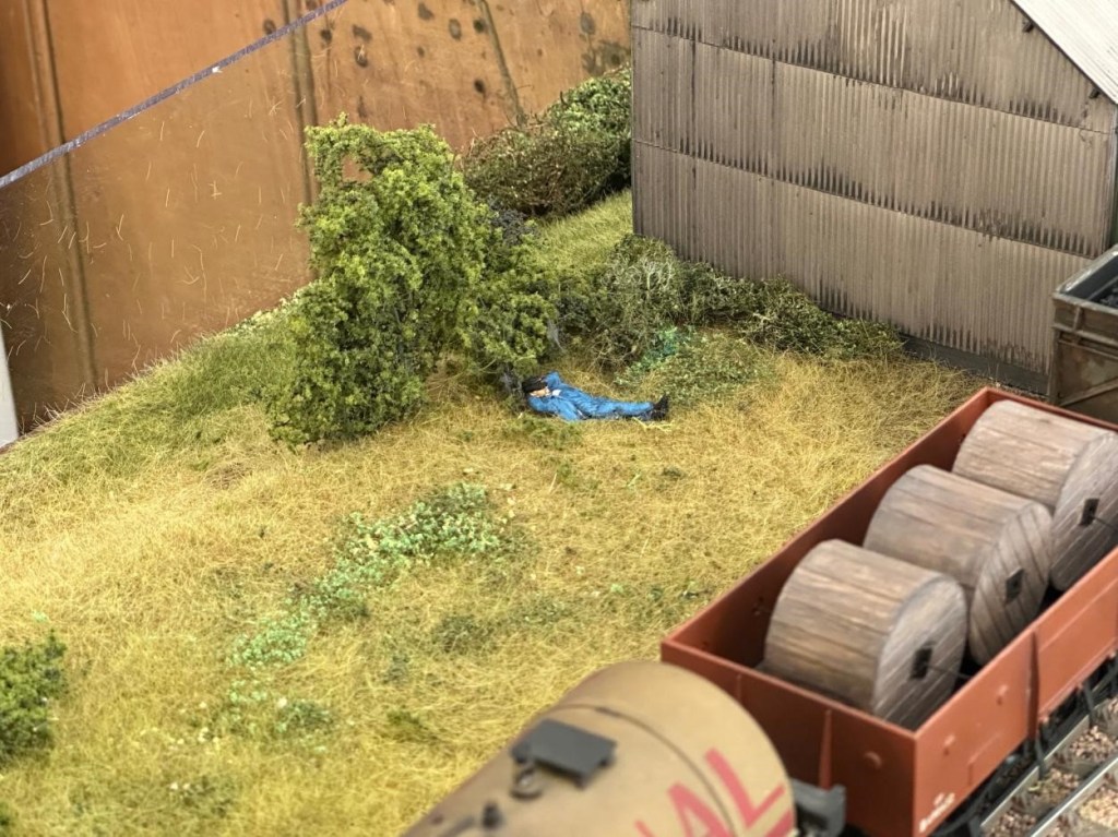
Finally, two further cameos at Lyme Regis:
Looks like a nice place for a snooze.
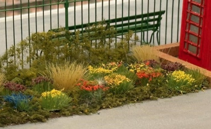
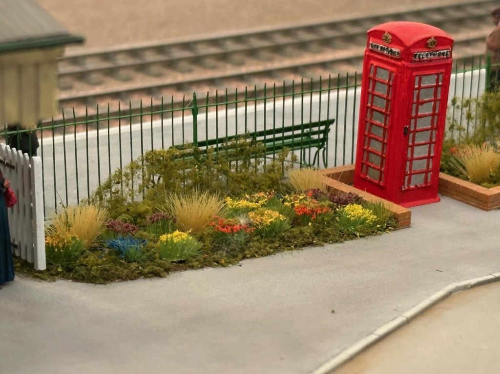
Is this the best flower bed on any layout in any scale anywhere?
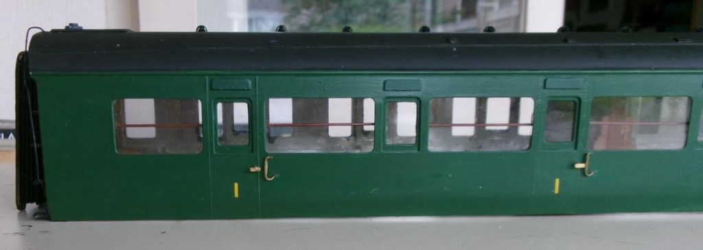
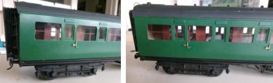
Pete C reports: The Maunsell coaches that the club bought from the estate of Simon K have had a few modifications and some repairs, one being a new bufferhead which had fallen off from a whitemetal buffer. A piece of brass was filed to shape and a spigot soldered in a hole in the buffer head to attach to the whitemetal housing. He then noticed that the cowling over the droplight windows had never been fitted, these were cut from plasticard and painted (luckily Railmatch paint was the same shade) then stuck on with thin superglue. The other noticeable missing items were the very prominent wooden handrails behind the corridor windows. Copper wire was painted and fitted to clips made from plasticard. The remaining job is to drill some holes in the solebar to secure the footboards properly.
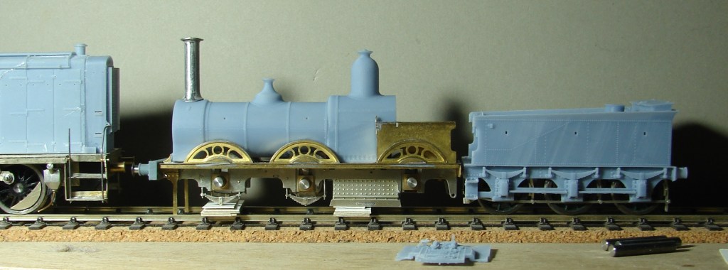
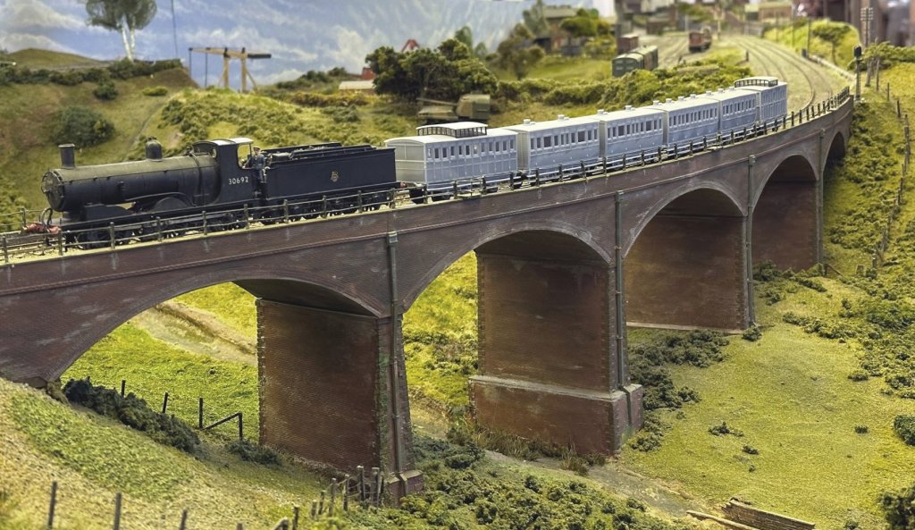
Steve has been steadily working through the many issues of 3D printing his LSWR coaches from the 1860s (in 4mm scale EM Gauge). Courtesy of Keith, not the Downton Train Crash formation of 1884, but a very close coupled rake of 3D printed coaches of all the required types crossing Bob Alderman’s viaduct on South Junction. The 1864 Passenger Brake is leading two 1865 Thirds, an 1862 Second and 1862 First, with the 1859 Passenger Brake bringing up the rear.
The Black Motor 30692 is the least inappropriate engine that he currently has to haul them, although it is at least a Sal&D engine. Built from a Jidenco kit by someone who had some idea of what they were doing and bought secondhand. The somewhat undercooked Jidenco 00 Gauge underpinnings were replaced using Persy chassis kits built to EM Gauge. Those familiar with Steve’s projects will guess that this could be made more complicated than it really needed to be: https://yeovilmrg.org/black-motor-re-chassis-in-em-gauge/
Finally Part 2 of the Big Bertha saga that could be a trilogy if it includes fitting the brake gear.
Jim has concluded that CS2 is not the best place to try and make something of the ‘Aberdeen White Elephant’, otherwise known as the ginormous 2mm finescale fiddle yard that I carted down from its namesake in north east Scotland (ie Aberdeen!) in the summer of 2019 and done little with since, due to (a) Covid and (b) his house move to Exeter in 2022.
Despite the loft in his bungalow having insufficient headroom to stand up in, and the loft hatch being unable to accommodate 8ft long baseboards, he has decided that he can make a better fist of it there than he first thought, and it will remove the need for regular 100 mile return trips back to Somerset.
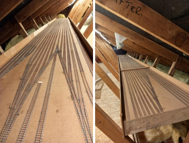
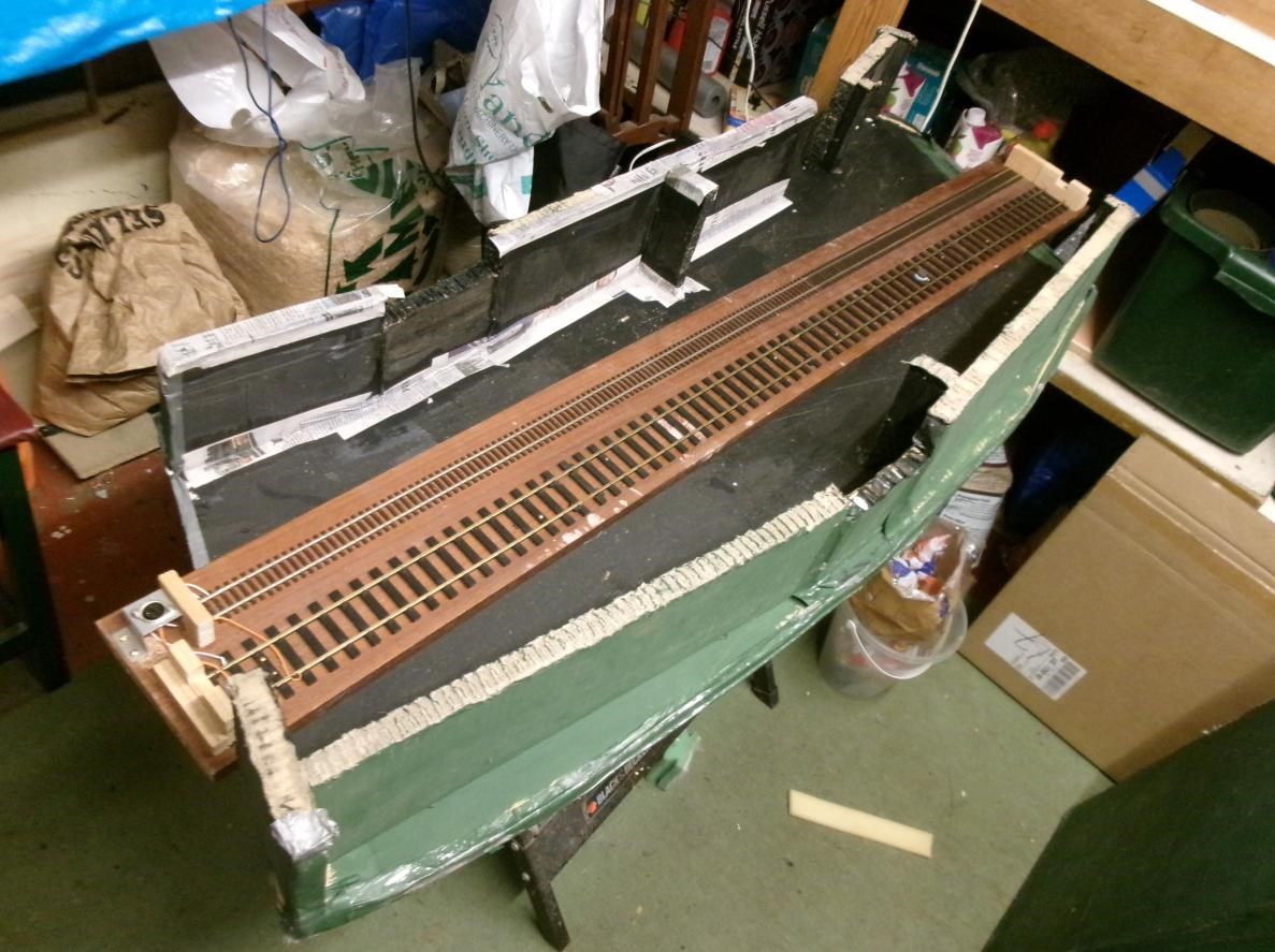
Accordingly, he ‘bit the bullet’ a few weeks ago and carefully cut a few millimetres out of all the rails (36 at every baseboard joint with 18 parallel storage roads) followed by gently sawing through the MDF baseboard top to convert three baseboards 8ft long into six baseboards 4ft long. All six boards are now up the loft at home and, simultaneously, I am adding raised flooring to gain access right down the length of one leg of the roof space. Below is a picture showing four of the boards, with two more to be added at the far end, before a corner is added:
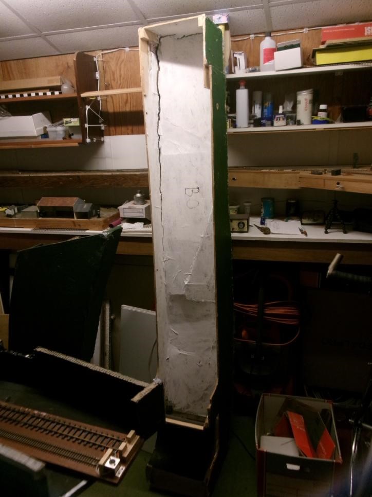
The second picture is taken from the other end and shows the fifth “half-board” added and more of the new flooring to the left. Of note is the relatively little vertical leeway Jim has to insert cross struts to support the boards more positively.
In May, the 2mm Scale Association is having its usual show at the Derby Conference Centre and this year it is all weekend, rather than just Saturday, and the star of the show will be Dunallander, which this fiddle yard was originally built for. Included in the van from Aberdeen this time will be the Perspex sheets that cover the fiddle yard boards which Jim forgot to collect in 2019!
A reminder that the scenic side of the layout has yet to be started but, in comparison, will be very simple and comprise a double track main line, with overhead 25kv catenary (!) and mineral exchange sidings and a branch leading to Littleton Colliery, near Cannock in Staffordshire. In contrast, the Grampian Area Group of the 2mm Scale Association, who was persuaded to save the scenic side of the original layout, have strived to construct an almost exact copy of Dunblane Station and its immediate environs, involving many, many buildings – see photo above at the Elgin Show. In contrast Jim’s rendition of Bungham Lane, Penkridge only needs one building, the junction signal box!
February saw Part 1 of the Big Bertha Repair ending on a cliff hanger see the link below:
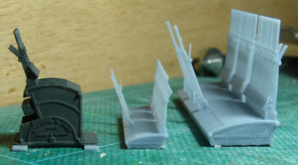
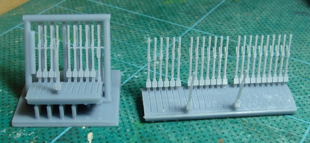
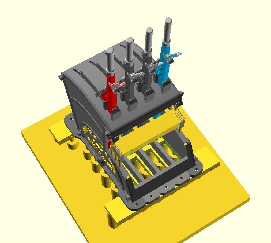
Steve is modelling Verwood in EM Gauge, and needed a Stevens style lever frame for the box plus a Stevens style Knee frame for the ground frame that was at the West Moors end of the loop. He’s 3D modelled these in QCAD and OpenSCAD and is 3D printing them in 4mm and 7mm scale on his AnyCubic Photon Mono 4K in AnyCubic ABS-Like Water Washable Resin 3.0. Both can be configured to have LSWR or SR style plates and with any number of levers. Could the models be 3D printed though?
This is a 7mm scale version of Steve’s 3D printed LSWR style ground frame for Verwood with some overly thick tails fitted to the locking frame. The clearness of the text suggests to Steve that his BR(S) smokebox plates (with curly 6s and 9s) could probably be printed vertically rather than on the bed allowing me to batch them up on a raft and remove and prepare them as required.
A test print showed that when tilted up on supports for 3D printing, the void under the tails needed to be more realisticly modelled (almost empty bar framing) so that it could drain of resin and water during washing. Win-win!
On the left a reject ground frame with coat of Humbrol Dark Grey to bring it to life. Also ‘Privett’ LSWR era frames in 4mm and 7mm scale with just the FPL levers reversed, as these frames were for most of the day waiting for something to happen. These sort of frames were not untypical of the Meon Valley and other somewhat overbuilt lines of the same period.
On the left a lever frame for Verwood in the final version of the support cradle. As with the ‘Privett’ frame on the right, what should have been the only FPL is pulled awaiting the next train – that was a mistake as it should have been Lever 4! The Privett frame was fairly easy to release from the final version of the support cradle with nicely aligned levers. It looks like some of the supports for the Verwood frame went AWOL but recovered just in time! There were a lot of iterations of the support cradle before it worked reliably every time.
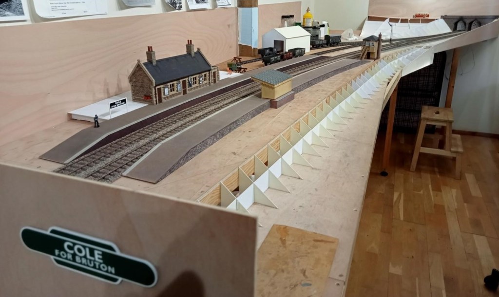
Allan is making good progress on his 7mm rendition of Cole. Platforms have been started and landscape formwork started. The platform surface was finished using fairly fine emery paper dusted with weathering powders (and brushed off outside as the stuff gets everywhere!).
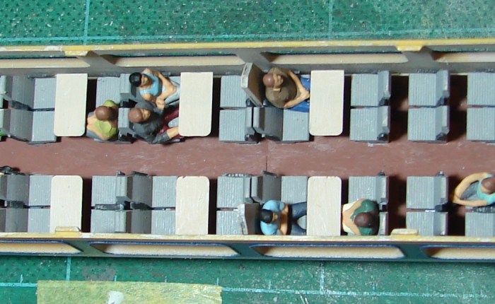
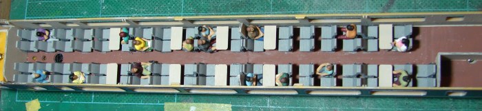
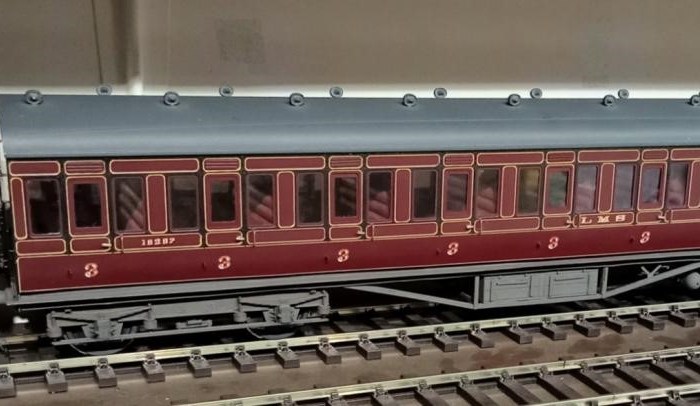
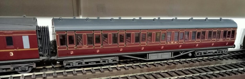
This is a recently acquired LMS Period 1 all third coach built and painted by the Sidelines man himself Malcolm Binns. Jim couldn’t resist it even though outside his period as the lining is outstanding. Unfortunately Jim had to refix the seating and entirely reglaze it – old model, old glue!
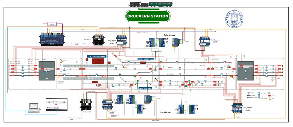
Plan of Proposed Layout
Andrew has been busy planning and ordering parts for his O gauge layout Crucaern Station (Anglo Saxon for Crewkerne. “Cruc” is hill and “aern” is a place or building). He’s taken delivery of a large box of points and track from DCC Train Automation.
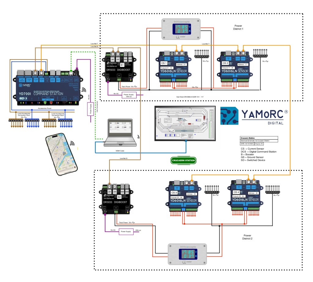
iTrains Control System Diagram
iTrains Schematic showing where everything needs to go
Below a few words to describe what should happen.
System Description for Crucaern Station O Gauge Layout The control system for the Crucaern Station layout is built around the YaMoRC YD7001 command station, which provides the DCC command signal, LocoNet communication, and accessory power for the layout. The layout is divided into two electrically isolated track power districts to improve reliability and fault handling. Each power district is supplied by its own DR5033 booster.
Track Power Distribution Track power within each district is delivered via dedicated red and black wiring from the DR5033 boosters. The two power districts are electrically independent, allowing one district to continue operating if the other experiences a short circuit.
Booster Communication (LocoNet-B) The boosters receive their synchronised DCC control signals from the YD7001 via brown LocoNet-B cables. These connections ensure all boosters operate consistently and maintain a stable DCC output across the layout.
LocoNet Communication Network A network of orange LocoNet cables interconnects the command station, feedback modules, boosters, and display units. This network carries system-wide communication including block occupancy data, device status, and accessory control.
Block Detection and Feedback Each district includes a combination of DR4088LN-CS and YD6016LN feedback modules. These units provide current-sensing and ground-sensing block detection, reporting the presence of trains to the control software via LocoNet. This enables automated operation, route setting, and visualisation on the layout mimic panel.
Accessory Power Accessory devices such as point motors, relays, and signals are powered using a separate accessory DCC feed from the YD7001. This keeps turnout and accessory operation independent from the track power feeds to ensure stable running.
Power Meter Displays Digital display units within each power district monitor voltage and current draw in real time. This provides clear visual status information for operators and helps diagnose faults quickly.
Control Interfaces The YD7001 connects to a computer for layout control software and to wireless devices such as smartphones and tablets for handheld throttle operation. A screen-based mimic panel provides a graphical overview of the entire track plan, including live block occupancy and turnout positions.
Technical Overview This layout is divided into two power districts, each managed and monitored to provide reliable DCC operation, feedback reporting and accessory control. The wiring scheme uses a combination of power buses, boosters, feedback modules, point motor drivers and signalling components, all coordinated through the YD7001 command station and LocoNet.
Power Distribution A pair of red and black solid lines represents the main DCC track bus. This bus supplies traction power to the entire layout. The bus is divided into two separate power districts, each protected and managed independently. Dotted boundary lines identify the equipment assigned to each district.
Boosters and Command Station The YD7001 acts as the central DCC command station. It provides: – Booster outputs (brown lines) feeding the DR5033 boosters via LocoNet B. Each DR5033 supplies regulated track power to its respective power district and provides short-circuit protection. – Auxiliary power outputs (blue and brown lines) used to feed point motors, accessory decoders and other low-current devices.
LocoNet Communication All digital communication between devices is carried by orange LocoNet cables, linking the YD7001, boosters, feedback modules and accessory controllers into a unified network. This ensures reliable synchronisation of power management, occupancy detection and signal control across the entire layout.
Block Detection and Feedback The track is divided into several blocks, each identified by blue labels. Every block contains two feedback sensors, represented by red labels, providing precise occupancy detection. These sensors report directly to the feedback modules via LocoNet, enabling automated signalling, route setting and train monitoring.
Points and Signals Turnout control is handled through green-labelled point motors, each connected to the accessory power bus and controlled via LocoNet accessory commands. Yellow-labelled signals are positioned at block boundaries or key junctions. They respond to feedback events and route logic, ensuring accurate line-side indications for both manual and automated running.
Overall System Function All components operate together as a coordinated digital layout control system: – The YD7001 provides command, logic and accessory control. – The DR5033 boosters supply isolated, protected traction power. – Feedback sensors deliver block-level occupancy data for automation. Accessory devices such as points and signals respond intelligently to LocoNet instructions. – LocoNet interconnects the entire system, maintaining consistent communication. The result is a fully integrated DCC control environment supporting automated operations, realistic signalling and reliable running across the layout.
Andrew also informs us that there are only two boards left of Heyno Junction to wire up before trains can run complete circuits! [Ed. Something I can understand!]
For the last few months most of the work at CS2 has revolved around getting Evercreech New ready for its second appearance at Taunton Railex. Happily its appearance was an outstanding success and the team involved should feel very proud and pleased, especially given the hard work involved. The Somerset Railway Modellers were brilliant hosts and Taunton School a superb venue with proper puddings. A few pictures from the event follow:
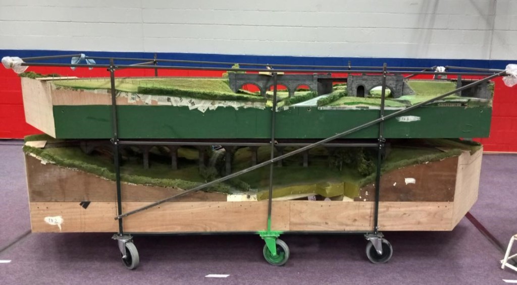
The infamous viaduct stillage (when loaded the size of a small car), with Prestleigh Viaduct on the bottom and Pecking Mill above. The castor painted green is key to the loading procedure – there are actually six castors on the stillage, and it has to be carefully pivoted on the outside edge of the tailboard on the green castor since the stillage is too wide to go in sideways.
This is why we do this!
The fiddle yard, with the operating area of other layouts behind.
Prestleigh Farm, which is unfortunately mainly hidden from the viewers by the viaduct, although Dave H constructed a high level background mirror to help with this. Next a few pictures taken during loading at CS2 and unloading at Taunton School:
With more scenery than last time, will it all fit in the lorry? Maybe……
The the new landscape boards (left) and original station boards waiting to be loaded.
Early stages of setting up on the Friday with a good three hours to go before it will be ‘ready to run’.
Meanwhile, In his large purpose built railway shed Allan has been working away at his new project, Cole (S&D) in 7mm Scale. The trackwork has been constructed from C&L components on plastic sleepers and the three way point was ‘particularly challenging’. [Ed. The ballast and colour of the sleepers I find pretty convincing, and doesn’t it flow nicely.]
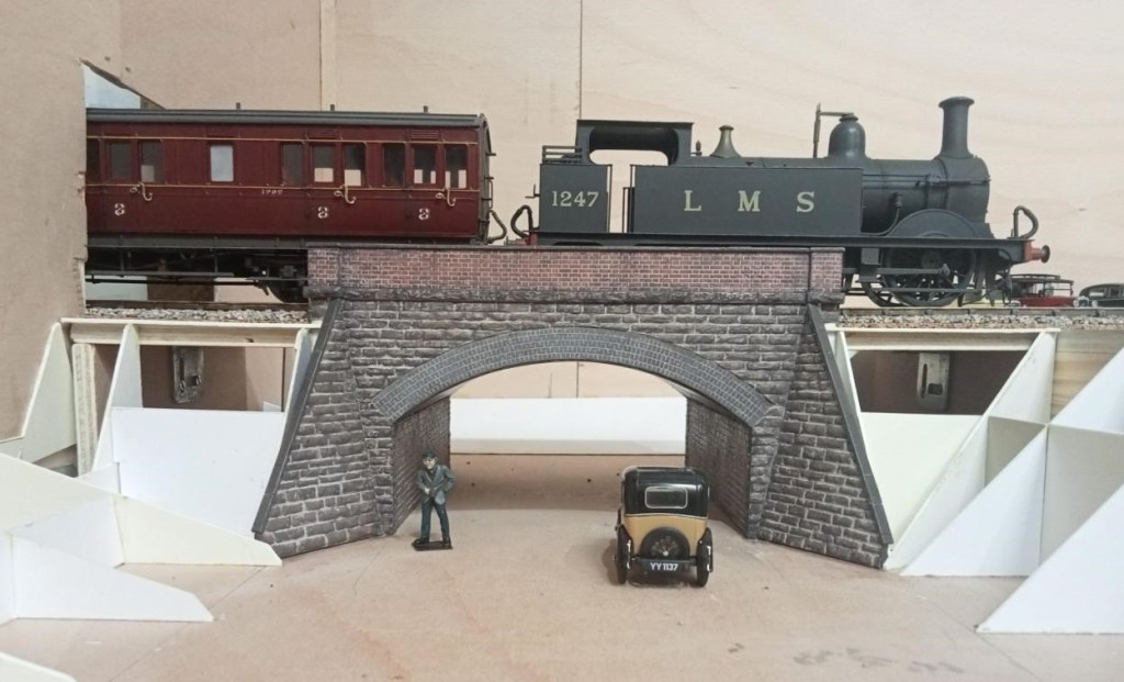
The bridge over the lane going up to Sunny Hill School. Will the Austin 7 need to reverse to make it up there? The arch was laser etched and cut by Mike of Jurassic Models.
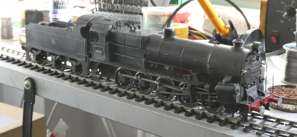
The project that has gripped Jim over this period was improving an ex-LMS 4F 0-6-0 which he bought some while ago via the Gauge O Guild ‘Sales and Wants’ on its website. A kit of some description, it had been constructed in true ‘Tri-ang fashion’, with the motor/gearbox installed horizontally so the lower part of the boiler had to be removed. Jim managed to re-install this with the motor sited vertically in the firebox some while ago, but he has now got around to filling in the missing part of the boiler and remodelling the inside of the cab so a crew could be added. A false floor was constructed out of plastic card to match the level of the tender and a flap of very thin plastic card added to bridge the gap. Hopefully the crew won’t now fall out!
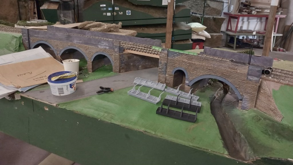
The main efforts in CS2 have been directed towards developing the scenery on Evercreech New ready for its appearance at ‘Rail-Ex Taunton’ in late October. At a recent visit to CS2, Allan took some pictures of the area around the two viaducts. As can be seen things have really started to come together on Evercreech New.
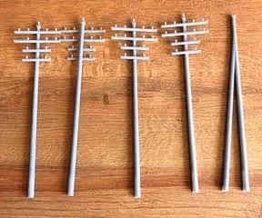
New bridge sections have arrived, made in a flexible ABS-like resin. They’re much easier to fit and are currently on the workbench getting some weathering treatment to help them blend in nicely. Over on the Pecking Mill Viaduct, the scenic team has been busy with the static grass, and the area is really starting to look the part. Fences and hedges have gone in too; which adds a lot of depth and character. Some very neat 3D-printed telegraph poles have been made up. These are destined for both the Pecking Mill section and the station area, and will add another great detail once in place.
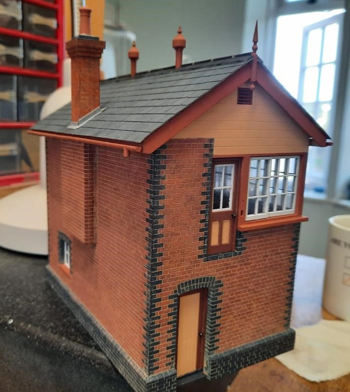
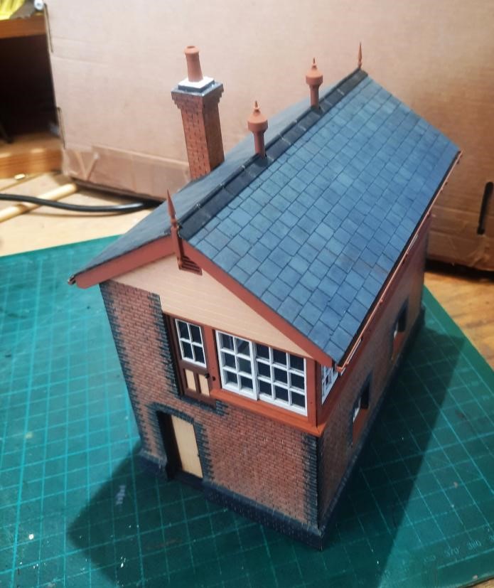
Dave H has been building a signal box from a laser-cut kit and now has the fun of the interior, using the etched brass kit from Severn Models
This reminded Jim of the signal box he had constructed some while ago for Littledean, from an LCut Creative kit, that included a full interior.
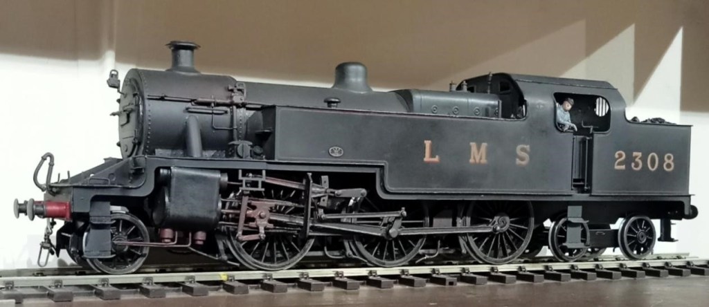
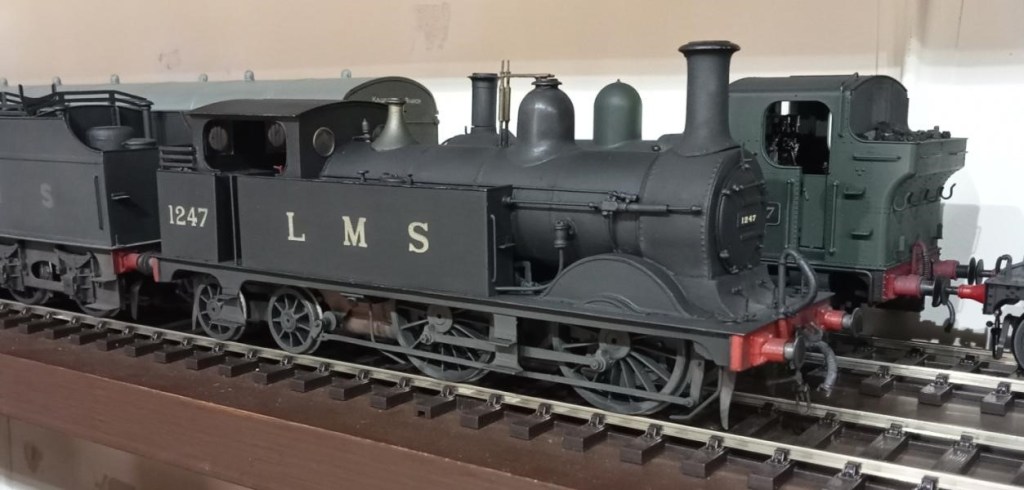
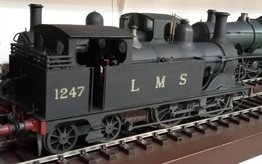
Allan has been beavering away at his 7mm rendition of Cole, and recently added an LMS 2-6-4T to his loco roster. Made from a Gladiator kit, the Fowler 4P has always been Allan’s favourite tank engine. He recalls seeing them in Manchester in his youth, but it is unlikely they ever appeared on the S&D. But what the hell it’s beautiful! [Ed. who wonders what that chimney is going to be when it grows up.]
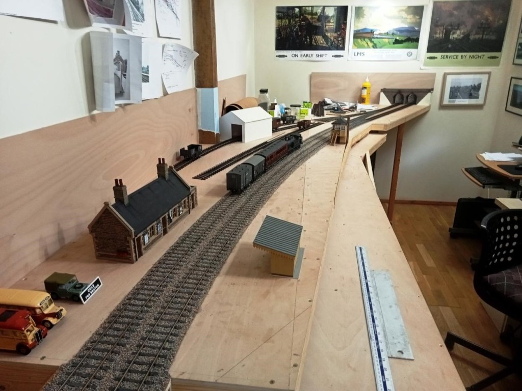
This is where Cole stands currently. There will be a hole in the shed wall beyond the overbridge so that through trains can run on into the garden – not much point in modelling a through station otherwise. [Ed. 0 Gauge in the garden – where there’s room for it – what’s not to like?!]
Although not quite finished, in May David S held an Open Day to show his superb new 7mm layout of Lyme Regis in its entirety.
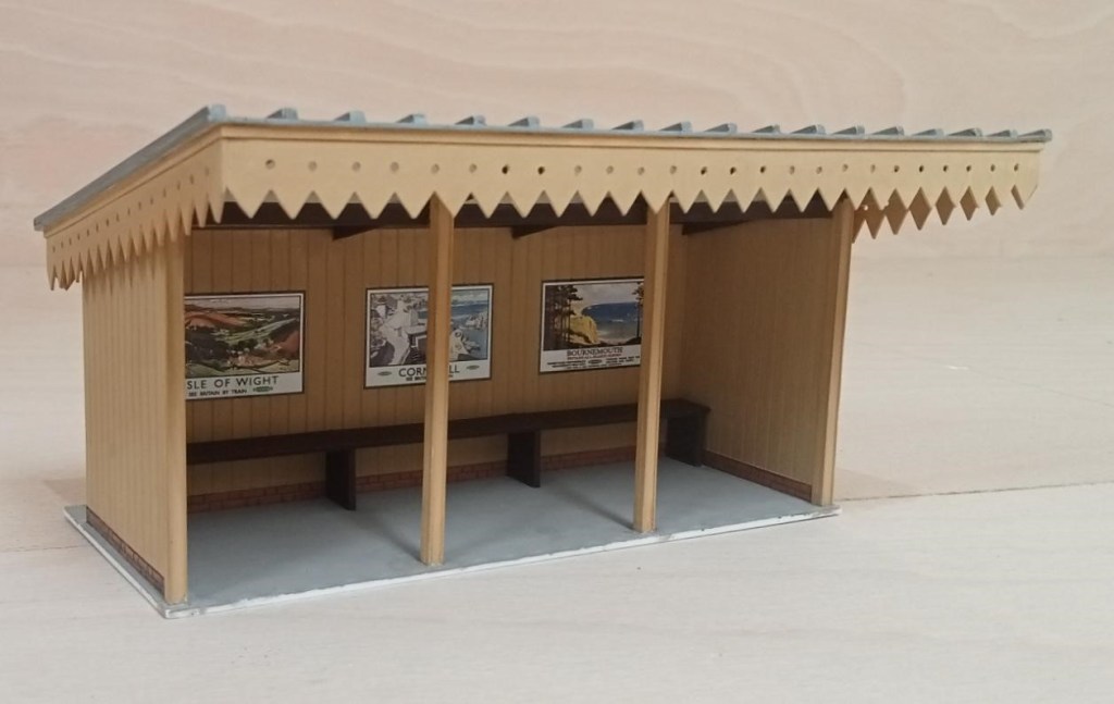
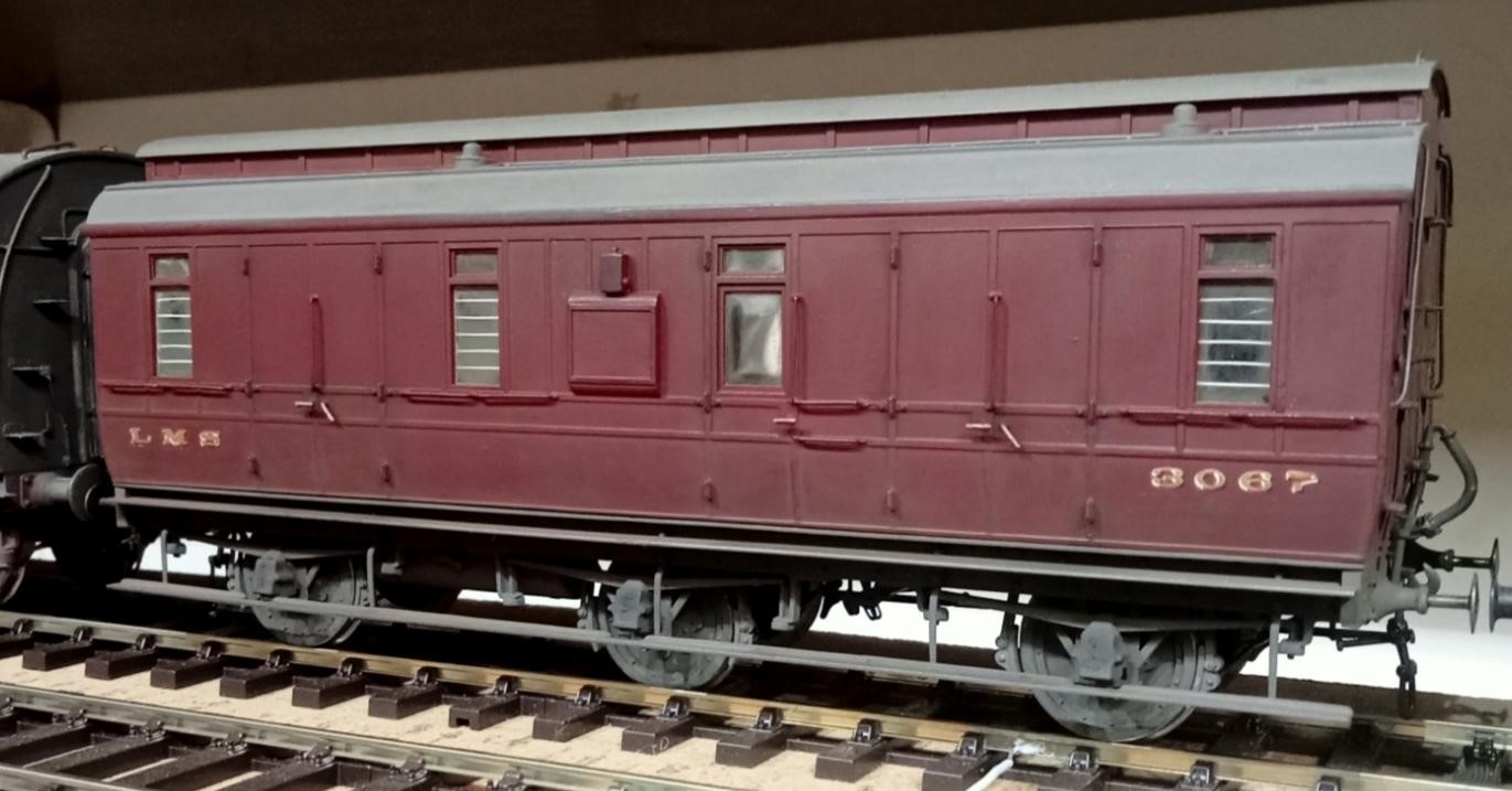
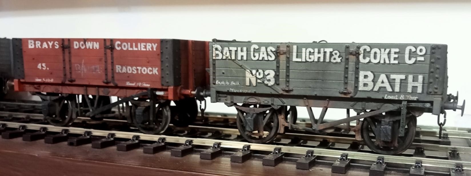
Alongside his work on Lyme Regis, Allan has continued work on his new 7mm layout and built the platform shelter for Cole (S&D) Station. Allan didn’t want to model the sag in the roof. Those props may well have been added to combat the sag on the real thing. Below is some additional rolling stock for Cole.
Since the last blog, The Summit has been exhibited at the two and a half day Bristol Show at Thornbury and acquitted itself well. Glimpsed in the background the scenic boards are back in their stillages and all hands have been diverted to Evercreech New which is due to appear at the Rail-Ex Taunton in late October.
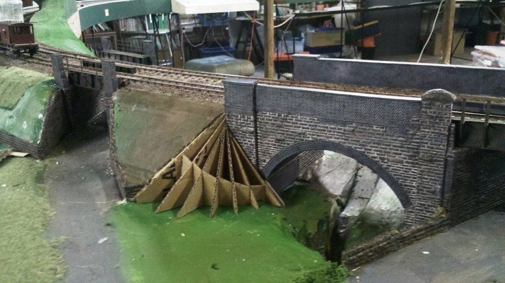
Pecking Mill Viaduct is a complex structure and a curve has had to be introduced to it so that it fits on our layout. Because of the curve the 3D printed girders for the skew bridges cannot be quite parallel or exactly the same length. All this has led to a potential lack of clearance if the girders are not precisely placed. There is a timber walkway outside the girder and the railings for those pretty much align with the outside of the piers leaving just enough clearance for model coach and loco overhangs. The girders may be very slightly outboard of where they should be as a result. The girders were printed in two halves, the farm bridge girders being similar but shorter, and it was vital (there was some confusion), that only the long half girders were used on the A371 bridge. (Ed. We kid you not!)
This wing wall was also replaced with an embankment – because there never was a wing wall there! The painting of the viaduct is complete, and looks good. Once the bridge girders are in place work on the groundwork, fencing etc. can start to make the place look real. There’s a good base layer of grass on some of it, it just needs a bit of variation, and longer grass on the embankment inside the railway fence. The road needs a camber on it and some attention to texture and colour, and there’s a small stone bridge over the stream needed too. Dave H was trying to explain Pecking Mill Viaduct to his father (he was a civil engineer). He thought it was something we’d made up as a modelling challenge, not a real place!
The scenery for The Summit was quite deliberately built ‘light’ as it only needs to hang off the rigid backbone boards that carry the track. This makes it vulnerable to damage as it’s ‘persuaded’ into and out of the stillages. Seen here, repair work is in progress with reinforcing of the tunnel boxes with paper mache joints. The scenery board has had the scenery detach from the frame for about 50%. Again paper mache, i.e. several layers, should be enough plus a couple of wood blocks glued in.
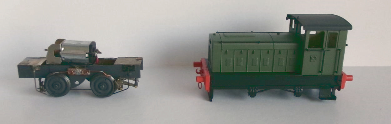
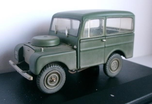
From Pete C, a 4mm Scale EM Gauge Ruston 88DS built from a Judith Edge kit, and perhaps more interestingly a weathered 7mm Scale Tickford bodied Land Rover intended for The Summit. These Tickford built Landies were marketed as a ‘Station Wagon’. They were better equipped than the standard Land Rovers and thus attracted Purchase Tax limiting sales. About 900 were produced, most were exported and few survive.
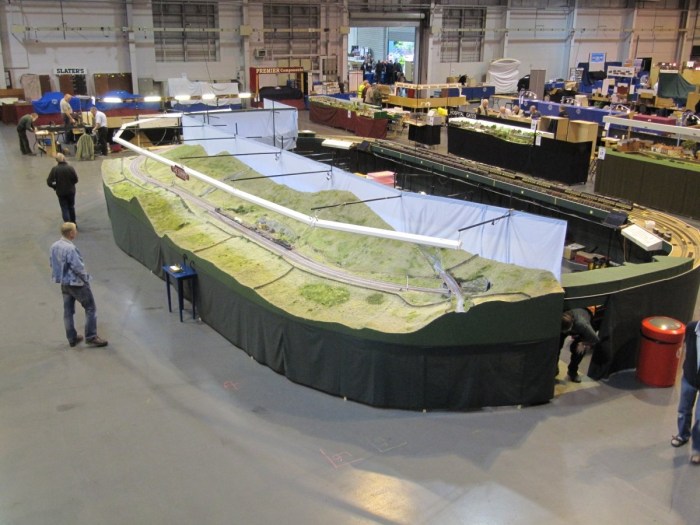
The Summit (pictured below at its first showing in Telford in 2015) will be heading to the Model Rail Scotland Show in Glasgow in February and our focus is now on getting this huge 7mm Scale 0 Gauge layout fully up to speed and ready for a three day show and a lot of miles in a 3.5 Tonne lorry – good job they come with tail lifts nowadays!
The Summit has also been invited to another three day show, the Bristol Model Railway Exhibition at Thornbury at the beginning of May, so some busy days ahead for the team!
Allan has added an ex-GWR small prairie, the preserved 4555 to his fleet of 7mm locomotives. Now fully converted to 7mm, he is advertising the sale of his lovely 4mm 00 Gauge layout “Kingsferry” in the next issue of ‘Railway Modeller’ and is planning an O gauge model of Cole on the S&D to replace it.
Dom has not been idle with his 4mm scale 00 gauge layout Combe Town, and recent progress can be seen above. He’s spent plenty of time building over 2′ of fencing along the front side of the railway (only another 4′ to go!), and has put the initial ground cover down in the field and on the yard surface. For good measure he built one of the Smith’s loading gauges.
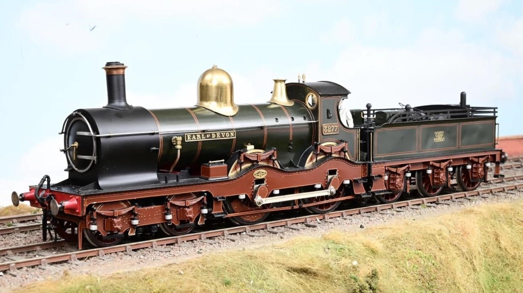
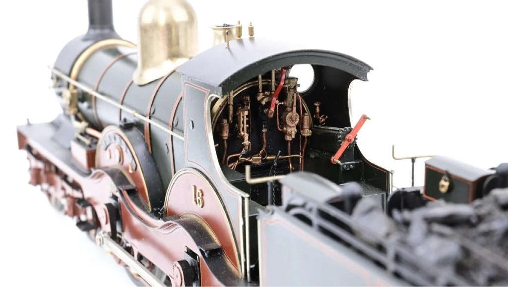
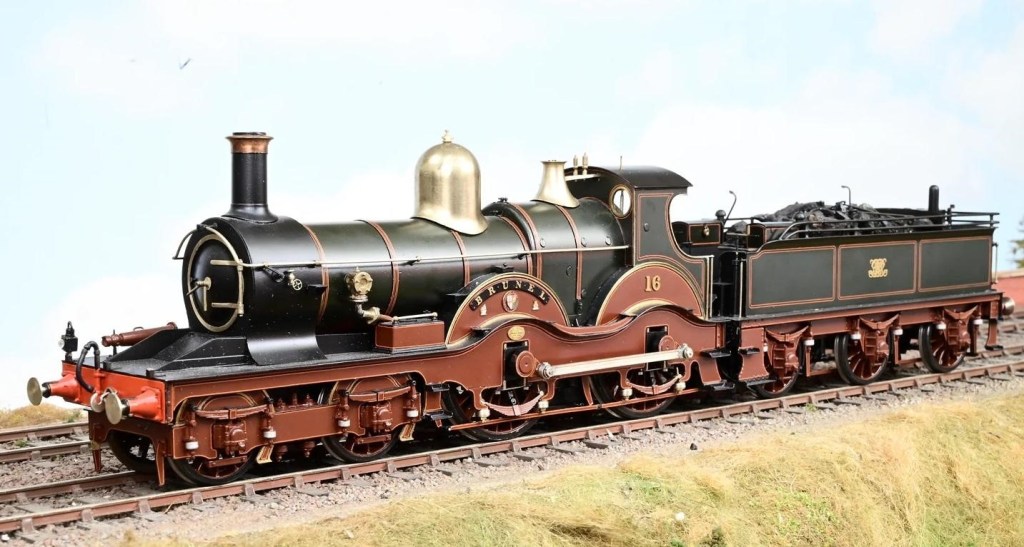
Your editor will spare his blushes as to why, but Dave H’s beautiful scratchbuilt 7mm scale Deeley 990 Class 4-4-0 requires complete replacement. It’s another 4-4-0, but this time it’s a green one – City of Gloucester as built in 1903. It’s based on a Finney kit but heavily modified so it can be dismantled for painting and maintenance, which is tricky for a double framed engine.
He’s also modified the tender so it will weigh on the rear of the loco. The tender underframe is mostly complete, and he’s made a start on the loco underparts. Dave reports that it’s a good kit and all is going well.
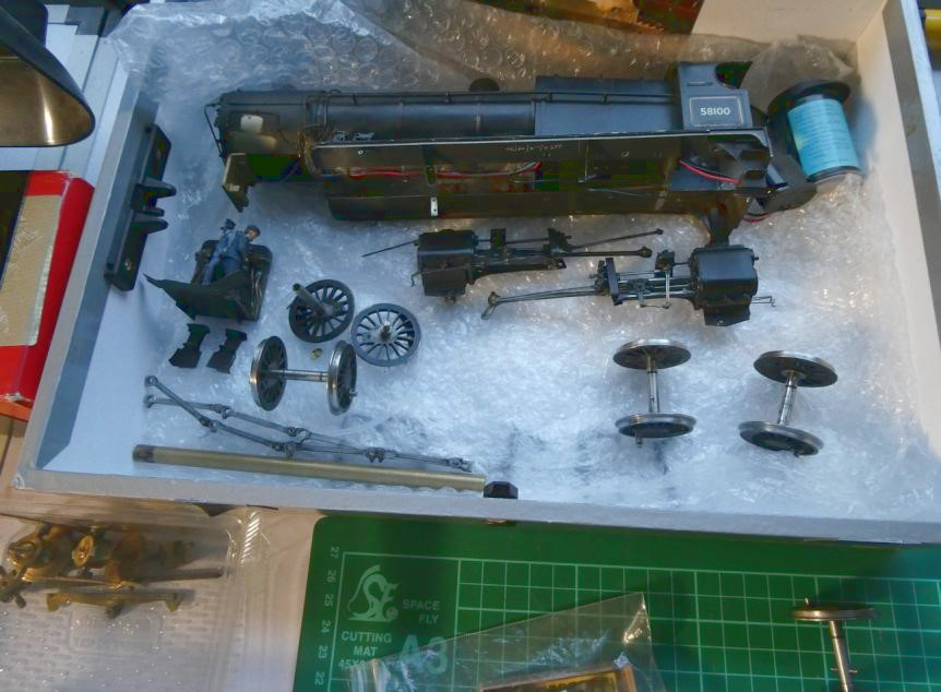
Continuing the ex-GWR theme, Pete C is finding the conversion of a 4mm scale Rapido model of a 15XX Hawksworth pannier tank to EM Gauge something of a challenge. This conversion is complicated by non-availability of wheels (they’re standard size GW wheels, but with a unique crank throw). The axle size is 2mm and the pickups are an unusual style of plunger pickup which has turned out to be unworkable with a widened back to back. The factory assembly wasn’t the best either, this engine having the same i.e. incorrect not handed coupling rods. The clearances proved just sufficient behind the crosshead by deepening the crankpin hole, which could then be screwed in another 0.5mm.
The wheels are pressed onto splined axles with top hat bushes which proved insufficiently long to reuse. Delrin rod was obtained and using the Unimat lathe new bushes were made by trial and error – more than enough were made to get ones that fitted accurately. Roughening the new axle ends with a file appears to have been sufficient to stop the wheel slipping on the axle. The original axle face was moulded on the wheel but was cut away allowing the bush to extend the whole way through the wheel and then trimmed.
New pickups were fitted to the keeper plate using copperclad glued and connected together by 0.35 brass wire on the top surface and reconnected to the circuit board plug through a new hole drilled in the chassis block. New return cranks have been filed from nickel silver sheet and riveted to the motion using Markits rivets. Only the front axle uses the Rapido screwed in crankpins, Romford crankpins have been used as the wheel threads were compatible. New spacers were drilled and turned to size, the return crank will be the final item reassembled after basic testing as they’re soldered on the crankpin.
As the conversion proceeded more and more parts were removed, it’s a good job an exploded drawing is on the web! The buffers are pretty poor and fitted badly, they’ll be replaced with brass ones. Otherwise the detail is excellent, including in the cab where it can’t be seen!
Derek is a fairly new member to YMRG. Recently he’s had some time on his hands, so he made a start building a kit he bought at Guildex in September. The kit is for an ash plant, and above are two photos of the work so far. He will replace the wooden railings (not shown) with wire ones, paint the model and then fix the roof on. This will eventually be used on a model of an LMS MPD.
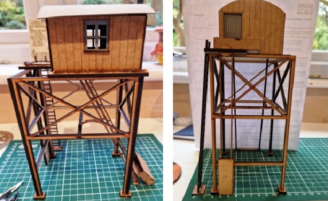
Simon K has acquired this 3D printed shed, coal store and water tower for a little quarry based layout that his wife and some ‘friends’ have decided will be a good project to keep him busy. Most of it will be built by a chap near Ludlow, but he will be doing buildings, people, stock and detailing as it suits him.
And this is Simon K driving Alice on the Bala Lake Railway.
Former Chairman Dave S installing the control panel on our 2mm scale N Gauge club layout The Bank with Hon. Secretary and Layout Co-ordinator Dean looking pleased, and Hon. Chairman Ed providing vital moral support.
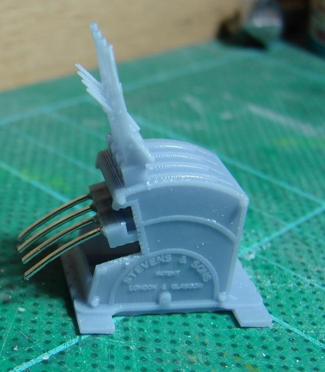
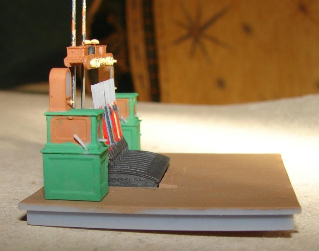
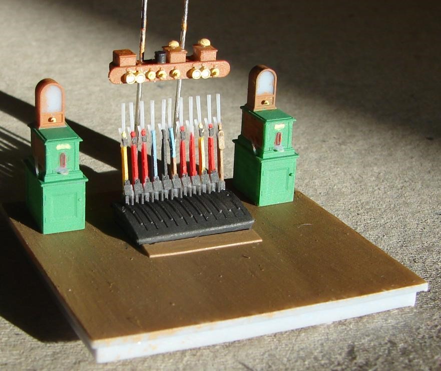
A couple of pictures from Steve of his 4mm scale 3D printed lever frame, instrument shelf, and Tyer’s No.6 tablet machines as once found at Verwood, cruelly enlarged to show how rubbish his current 000 brush and eyesight are. Any brass has been painted light yellow which seems to work well. It was anticipated that ‘STEVENS & SON’ would be legible after painting, but one can just about make out ‘PATENT’ and ‘LONDON & GLASGOW’ underneath, though the letters are much fatter than they should be due to ‘additive kerf’ – something (that regular readers of the blog will know) makes holes smaller and rods larger in 3D printing.
The levers are incredibly delicate and a comb like jig had to be devised to hold the levers in place whilst the supports were removed; even then, Lever 6 pinged off where it was nice and thick and has had to be glued back on so is wonkier than the others. There is scope for further straightening with the warmth of a hair drier. This lever frame would even better printed in 7mm scale where the levers wouldn’t need to be quite so plump. the number of levers can be varied and alternative lettering is possible for other makers of Stevens & Sons style frames.
One of the plunger buttons is missing from the shelf – it probably came off with a support, and no attempt was made to portray the coiled spring for the gong at the left end – a coil of fine wire being the only option. If it had been realised that the handles on the release lever had come out on the tablet machines he’d have picked them out in black, and I would have dotted the labels above the repeaters if I’d been able to see them. He’s left the steel bits of everything unpainted whilst he contemplates what colour steel should be. The steel poles supporting the shelf at 0.62mm are clearly too thick and should be painted green.
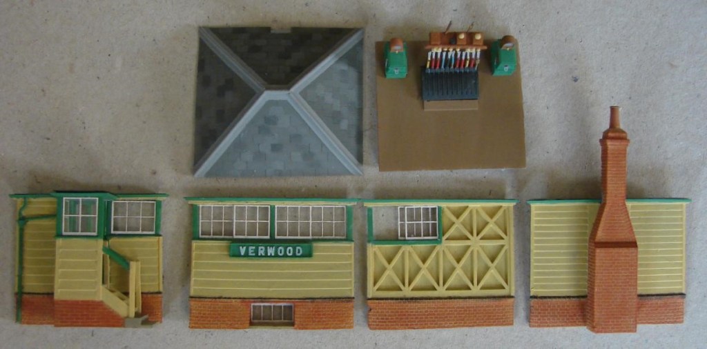
Next up is the painted parts of the Verwood signal box ready for assembly. There are some mistakes. I failed to order the cupboard with desk, pen and register, and need to pick out the lower string course in dark grey, as well as all but one set of brick quoins.
This being Verwood there’s no weatherboarding to the wall under the canopy and no drainpipe on the basis that it drained onto the attached canopy. Jurassic Models cut the sash windows for me and they really look the part and fit well. The sashes had to be redrawn to fit the 3D print and then again to allow for the heavier kerf of the laser used. Due to additive kerf the ‘VERWOOD’ lettering on the 3D printed sign is a little too heavy so I’ve redrawn the lettering 0.05mm less all-round and will re-order.
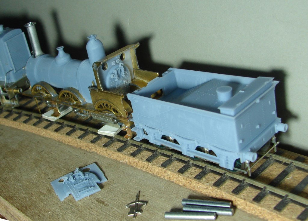
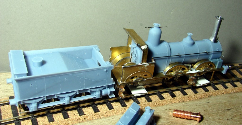
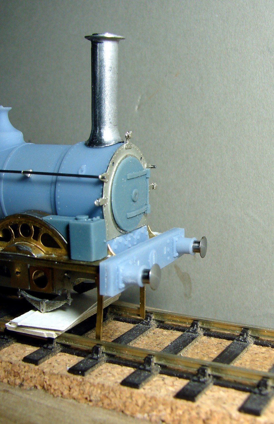
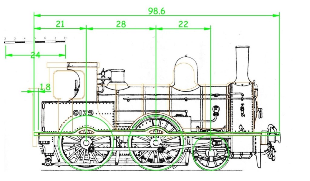
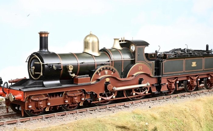
Now for something completely different – cue Monty Python! When the Beattie Well Tanks were being retired from suburban service in the 1880s, thirty were converted to tender engines using Beattie 1950g tenders – those that have been paying attention to these blogs will have know where this is going! So above is the resulting engine with Adams style cab, overlain with a tracing of the Eastleigh Weight Diagram for a Beattie Well Tank in orange. The tender engines were shorter at the front (not having been rebuilt with frame extensions and steel buffer beam), and have pierced splashers, shielded safety valves, different dome and chimney, but otherwise compare well. The green lines are the Kernow running plate and splashers. The intention is that an etch will be designed to replace the cab unit on the Kernow Beattie Well Tank, and to further this, the necessary parts have been drawn up and will be test built in tinplate by a fellow enthusiast for railway engines of the 1880s.
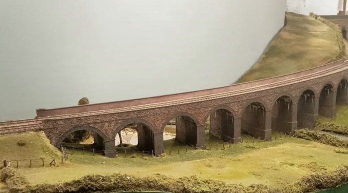
Lastly from Steve the three stone pier caps for Pecking Mill Viaduct (see above). A styrene armature forms the arrises and Milliput was used for the lumpy bits. The many brick pier caps needed will be 3D Printed, and the long runs of brick capping for the parapet will be laser cut and etched.
Jim’s LGP (Last Great Project) tentatively titled Bungham Road, will be a 2mm finescale rendition of Littleton Exchange Sidings at Penkridge in Staffordshire, set during the mid 1990s. This is a photo of the prototype, taken by David Rostance from Wolverhampton in 1985. The new layout will be housed in the space vacated by Halsdon Road after its move north.
A picture of the superb second hand fiddle yard boards that Jim has sourced for this project, when they were briefly erected in CS2 back in 2019. Rumour has it that Jim already has more than enough stock to fill all those sidings!
August saw another excellent Railwells show. This year YMRG was represented by Susan’s S4 layout Buntingham.
Based very loosely on Buntingford in Hertfordshire, it was built in the 1970s by Susan’s father Ray Hammond, a founder member of both the P4 and Scalefour Societies. In this photo Susan can be seen doing something very important in the fiddleyard, whilst fellow operators Dave H (nearest) and Steve both in YMRG shirts are wondering which knob to turn, or lever to pull or push next. Two very enjoyable days, and the layout was well received.
Regular readers may recall a recent feature on a 3D printed obscure ex-LMS Armstrong Whitworth diesel loco which Steve designed and constructed in EM. This is the mk2 3D print (and nearly finished product with the flush glazing sticking out of most of the glazing pockets) plonked on the track at Buntingham. Looking at that bend in the bonnet highlights how 3D printed resin whilst brittle is also oddly flexible when you’d really rather it wasn’t!
Allan has finished constructing his LMS Johnson 1P 0-4-4T from a Slaters’ kit – and excellent it looks too:
Our former Chairman Dave S has been wiring the control panel for The Bank (TB), the club’s N gauge layout based on Hemerdon Bank in South Devon. These are nearly finished and he will be bringing them down to CS2 soon.
The power supply for TB. It provides power for the controllers, the LEDs, the relays and the point motors. It has a couple of spare outputs, 12v DC and 16v AC.
The bare panel top prior to the addition of switches etc.
The underneath of the bare panel. Note that all the push button and LED positions are marked for ease of finding them for wiring.
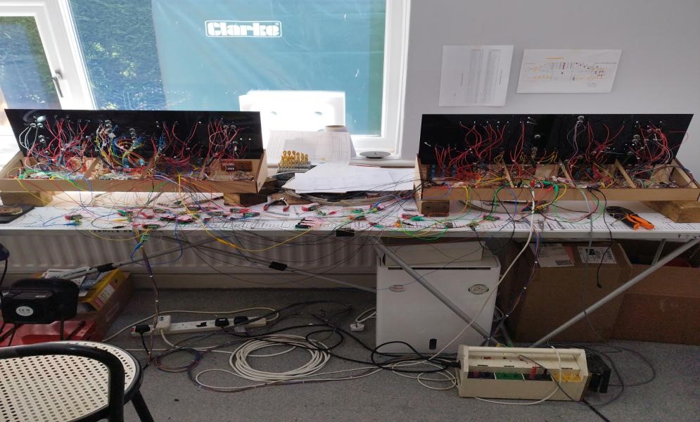
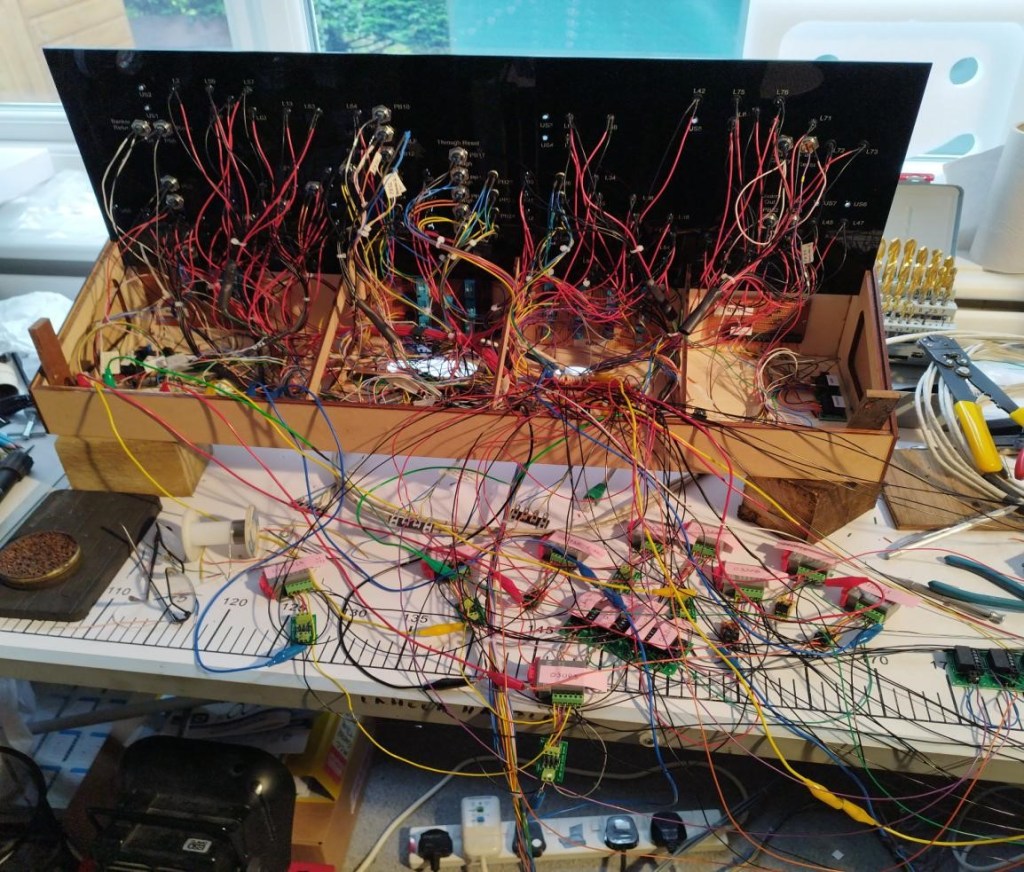
The finished panels in testing mode with a rats nest of wires connecting the panels to point motors etc to simulate the layout.
A closer picture of the Up panel. Note the MP1 point motors in the foreground.
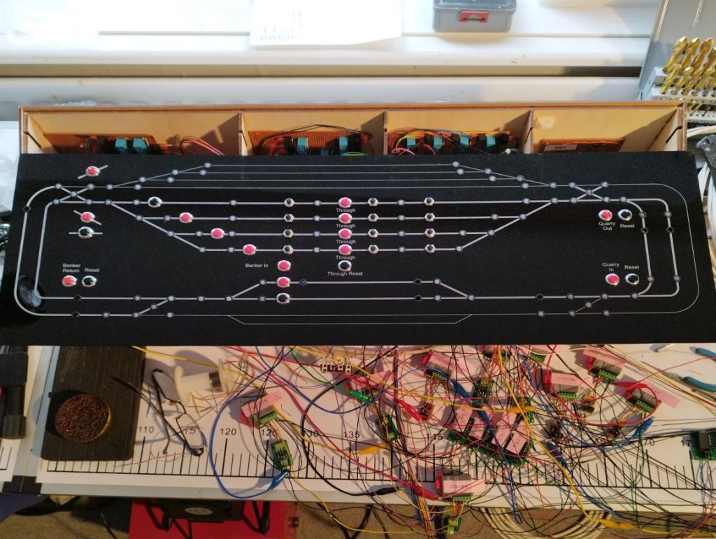
The finished top of the Up panel. It will fit the box underneath when installed on TB.
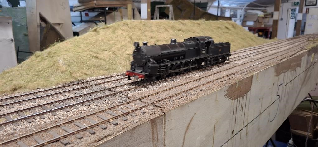
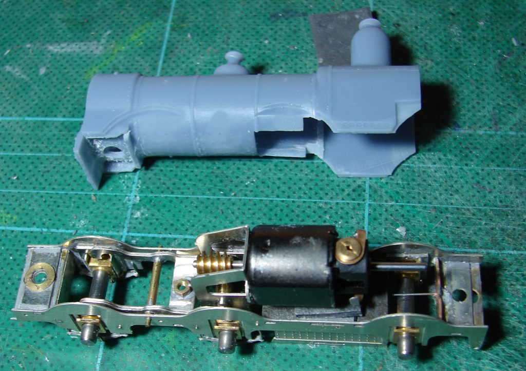
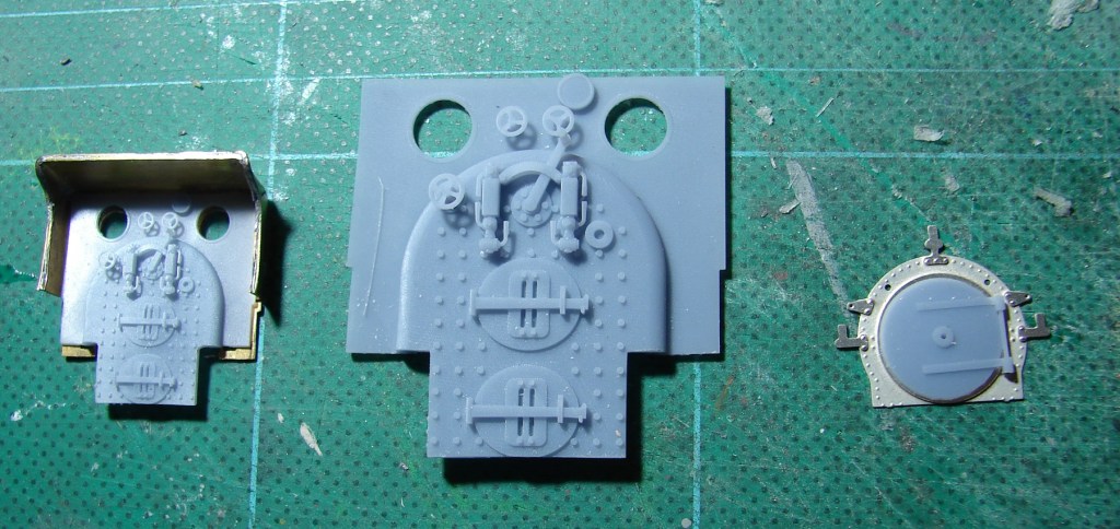
Steve will be building his K’s Falcon Class as Vesuvius Class engine 294 – the train engine for the Downton Crash Train. One problem with the K’s kit (the relevant bits of someone else’s complete kit shown above), is that the rudimentary chassis is about 1.5mm too far forward in the whitemetal body, cunningly disguised by making the front about 1.5mm too long. The rear splasher is the correct length, but the coupling rod splasher moulded into it is 1.5mm too far forward, so needs a cut and shut to move it. It took ages to spot this error as the coupled wheel base is also correct, and it wasn’t until it was realised that the sandbox covered far too much of the inner front springs that the error was finally spottted. The aim here is that everything will end up in roughly the right place, as that’s more likely to look right. The changes to the splasher unit don’t stop there, as the front driving wheel splashers on 294 weren’t pierced, didn’t have any sort of trim round them and the coupling rod splasher swept down to the running plate without that step. Between the splashers where the Falcon had an exposed donkey pump, the Vesuvius Class had one that was all boxed in to match the rear splasher.
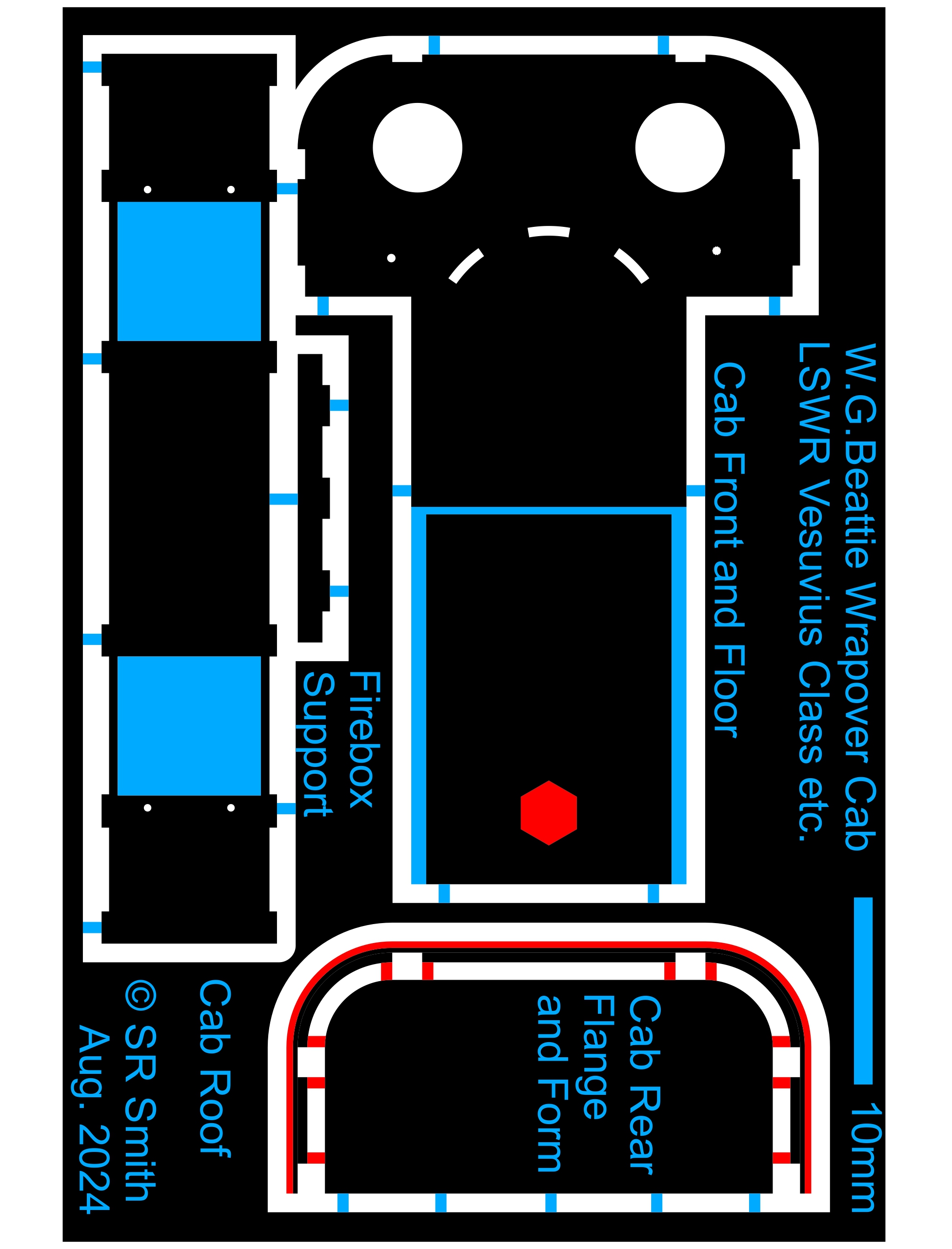
Below is the home made artwork for all the etched parts that Steve thinks is needed to make a Vesuvius Class body from a Falcon Class kit. All done in QCAD, it was a steep learning curve to work out a method to allow for cusp, and put in moats and tabs in a way that was fully reworkable. Black is no etch, blue is half etch from front, red is half etch from rear, The phototool is a one off, up-front cost, enabling about five copies, It was thought that a modular approach was the way to go, but with the minimum order being a 290mm x 135mm sheet, these two plus the three larger etches to build the engine and tender chassis, almost fill a sheet to make one big etch. This means that any revisions from the test build will require a completely new phototool.
294 had the flat top Stirling style cab, and being EM Steve can spread the rear splashers a bit so has provided a wider etched floor. The rear driven axle is very close to the cast floor, and to provide clearance for the twin compensation beams he will narrow the K’s casting under the cab. The etched floor with soldered nut provides a better fixing and permits this approach.
The boiler was raised about 3″ compared with a Falcon, so a more accurate smokebox front with a sort of saddle to lift the smokebox and better simulate the exposed front frames seemed the way to go. On the prototype the buffers are bolted to the frames and the toggled extensions on the cosmetic frames will accept the K’s buffer beam as part of the body – this is much more convenient for a model. The new front allows the smokebox to be shortened (no visible rivets on the smokebox sides), and this also allows the other ways in which the front was too long to be addressed.
In June St. Martin’s Wharf” returned from a very successful appearance at the Shepton Mallet Show, where it won a trophy for the best scenic feature.
All credit to Bob Alderman who created the layout – and to the members who renovated it!
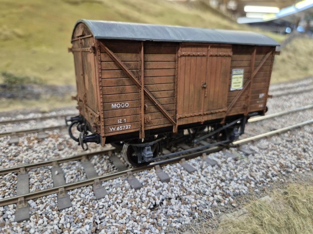
At our annual competition the Chairman’s Cup was won by a 7mm modeller. Well done Keith S, for his ex-GWR MOGO.
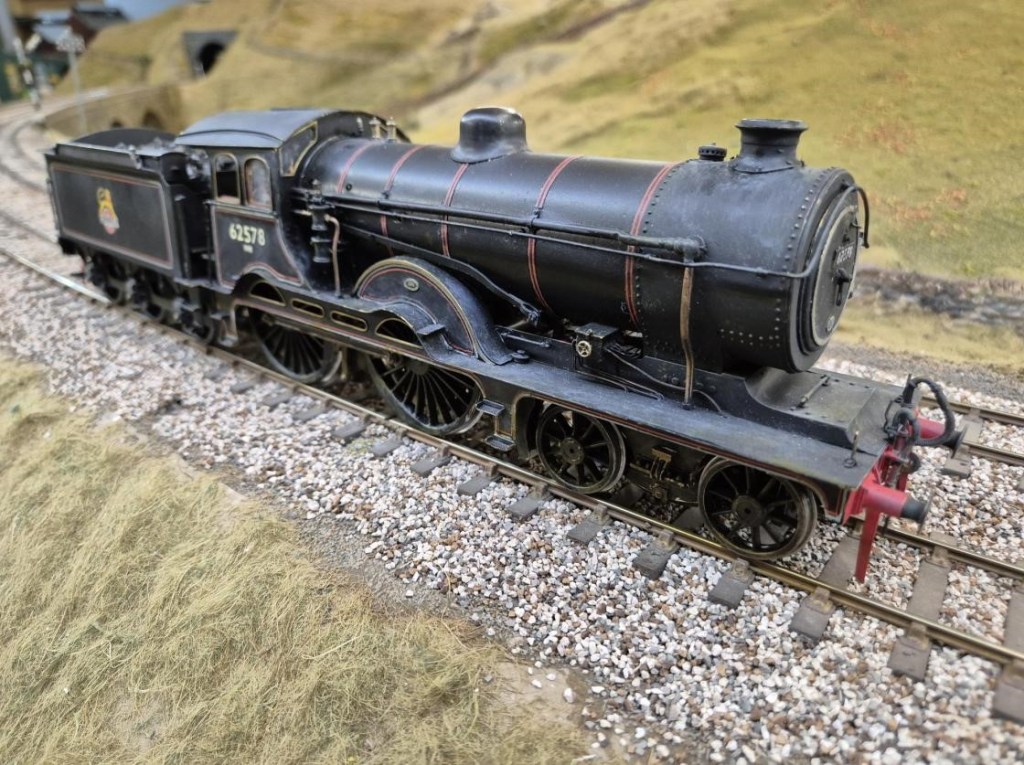
The Ernie Phelps Cup for Locomotives was won by John M for his 7mm scale LNER D16/3
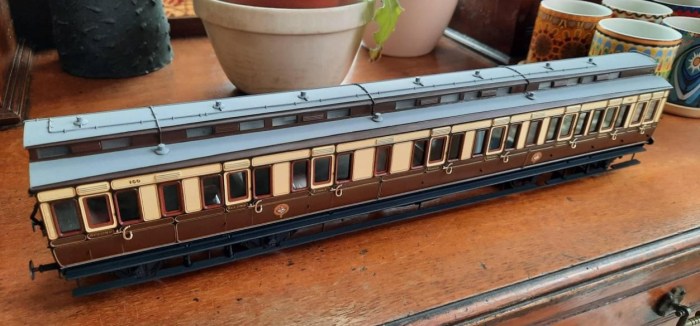
The Brian Draper Memorial Cup for Rolling Stock was won by Dave Haines for his 7mm scale GWR Dia E57 Lav Tricomposite Coach
Highly commended – Pete’s 4mm scale EM Gauge SR 15T Brake van and Trestrol, and the Coker Cup for Railway Related Items went to Keith B for his hand built points on Heyno Junction.
Dominic has made plenty of progress on Coombe Town. Firstly the station showing the signal box with its glazing and the platform buildings. The headshunt is now ballasted, and he has completed the majority of the sculptamold landforms. The signal box has also received its final large windows today – the next final major exterior piece will be the porch. He is now happy with the general approach to take for Heyno Junction box so will make a start on the actual model there once the size is confirmed with Keith.
The second is an overall view of the layout, to give an idea of the progress to date.
There has been much debate around the lime works at the rear of the station and Allan has taken it upon himself to organise the narrow gauge quarry wagons for the works. After much deliberation, he has ordered the above tippler wagon from Smallbrook Studio.
This is a photo of the lime works that Allan took when the layout was still in Julian Birley’s ownership. Some ‘bright spark’ had the idea of placing Prestleigh Viaduct just to the right of the road bridge necessitating some adjustment to the position of quarry and lime kilns to make it all fit again.
This month some ‘proper’ modelling, followed by ‘virtual’ modelling.
Allan has finished another of his 7mm scale LMS coaches, this lovely example, from the single window with square corners would be a period II corridor third – from another Sidelines kit.
Obviously relishing the challenge of turn-of-the-last-century intricate livery paintwork, Dave Haines has produced the next 7mm scale coach for his “Wellsy” layout. This one is a 58 ft long luggage tricomposite, originally built in 1899 for the Birkenhead to Folkestone/Deal through trains run with the SER. They turned out to be very useful as through carriages all over the system so they built twenty of them in the end. They had six lavatories so it’s surprising there was any room left for passengers let alone their luggage! It’s all plastic except for the Slaters bogies (the long wheelbase version that Dean used for his later coaches) and a few fittings, scratch built using David Jenkinson methods and painted using Ian Rathbone methods.
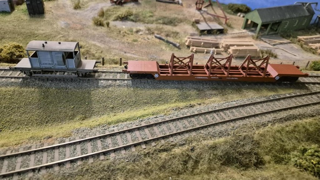
A few evenings work by Peter has dramatically improved the 4mm scale EM Gauge Accurascale Chaldrons that he bought a while ago. Subtle weathering has bought the detail out from the original plain black satin finish.
Over the last month Andrew has been working on the flyover bridge for Heyno Junction, the club’s OO gauge layout. It is based on the Aynho Flyover on the Chiltern line. The model has been produced in Fusion360 CAD software and he has started to print out the brick base on his 3D printer. It has been really tricky to do the brickwork as the process makes the computer struggle with long waits while the computer worked out the pattern (he could do with a more powerful computer). The first section took over 20hrs to print out and the 2nd section took over 17hrs. He has started to build up the metal work of the bridge into sections so they can be printed out and assembled
Whilst at CS2 Steve gave his 3D printed AW diseasel disaster a run out on South Junction, which it plodded around for about an hour without managing to fall off. This was after its trip to Martin Finney’s Semley where this model to EM Gauge serenely clambered over and through two sets of P4 points in both directions without derailing. During this feat it was noticed that after 18 years the original tyreless AG gearwheel had cracked and slipped on the jackshaft axle leading to a slight ‘hop’ on each revolution. This gear wheel has now been replaced by its previously redundant twin (on a slightly shortened axle) with the steel rim retained, the spokes covered over, balance weight fitted and the flange filed off. Steve hadn’t appreciated that he needed macro mode on his new to him Sony camera (2011) for it to focus properly for a shot like this that he wouldn’t have previously considered any sort of close up.
The glazing pockets on the trial 3D print were not satisfactory as I hadn’t made enough allowance for 3D printed items being a little larger than specified – by about 0.1mm and mainly a problem with holes. Thin bubble packaging film could be slid into the side window and door glazing pockets, but not into the front and rear window pockets. To get round this the pockets are now 0.45mm (for .010″ Plastiglaze), and holes have been added above the affected windows to aid resin drainage during printing.
To aid the printing process a sliver of extra material has been added at the bottom of the body for trimming. The fuel and battery boxes have been boxed in, and braces placed across the base of the bonnet to keep everything aligned during printing and cleaning. This render pre-dates that test run on SJ with the larger gear wheel that has required additional clearance to be added under the gear wheel cover.
Lastly a helpful Western Thunder user posted a very useful and clear photo of the prototype from a new angle from which detail could be added to the gear cover area (speedo drive cable and oilers). I also used it as a reference to develop some artwork for the WD transfers.