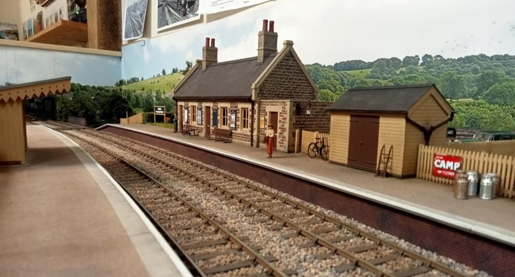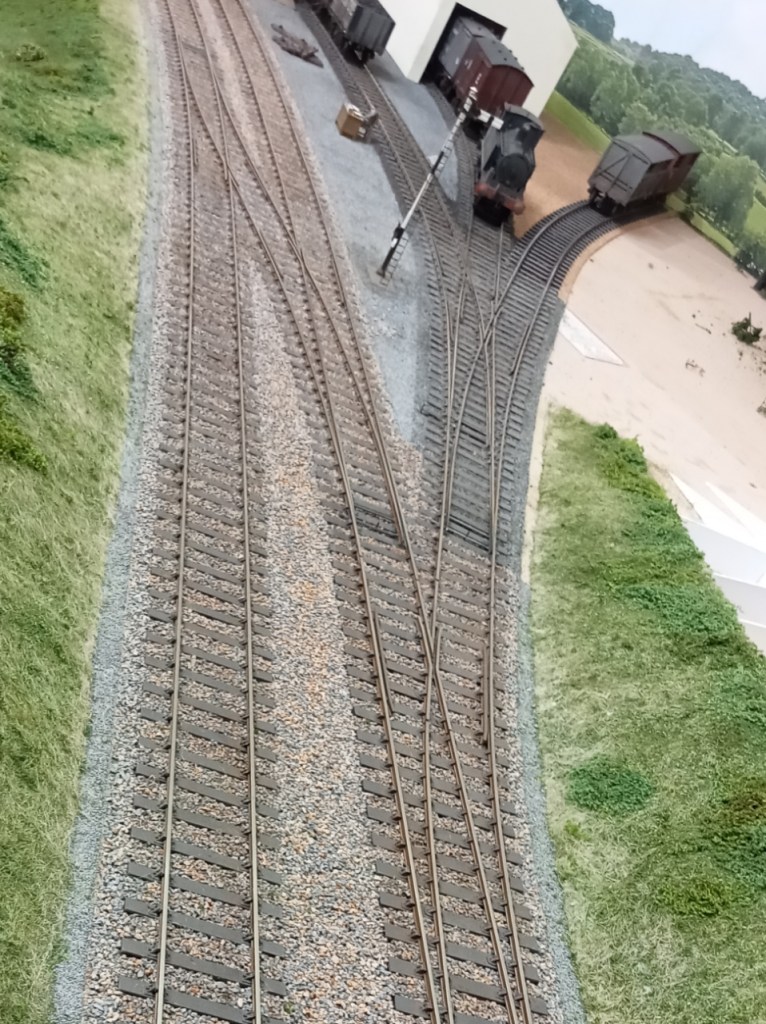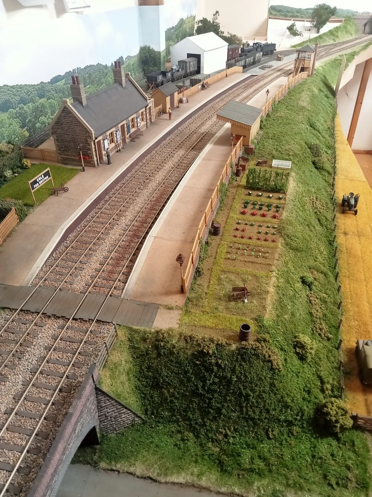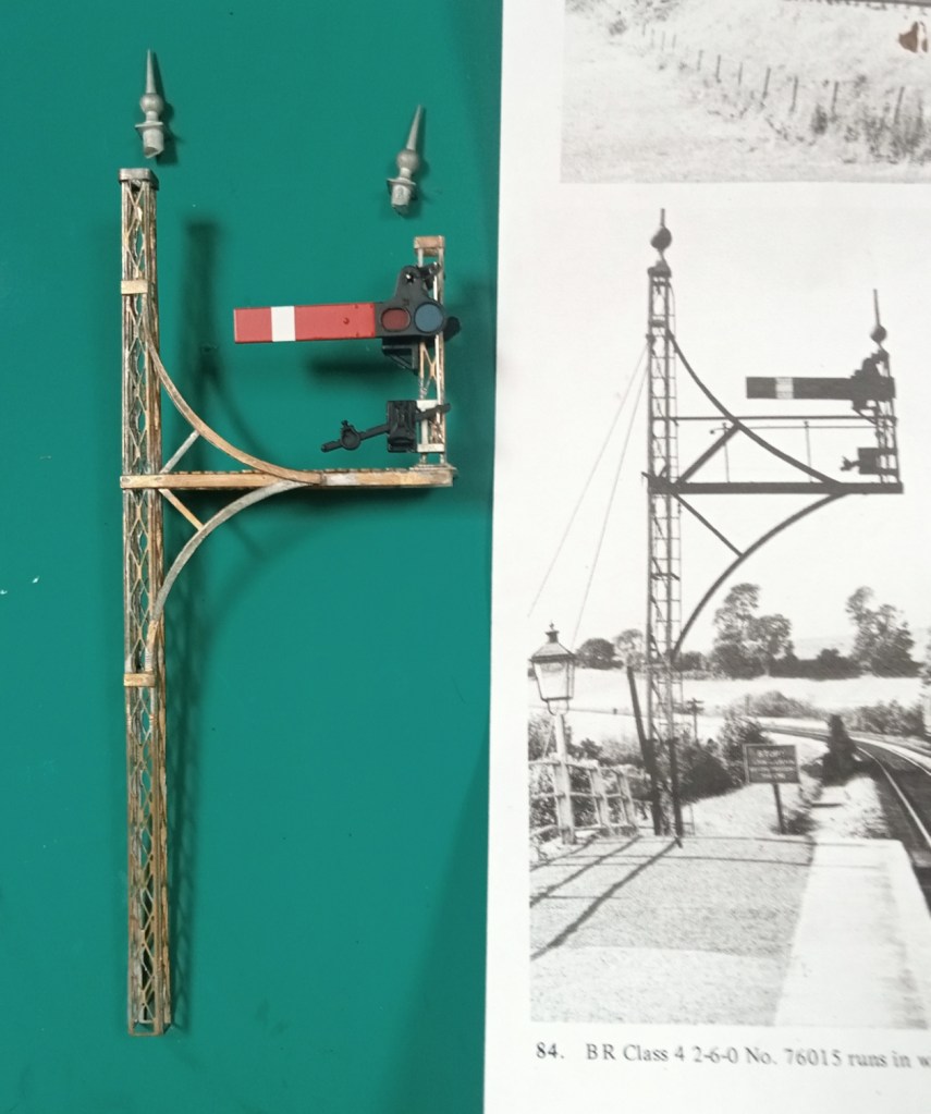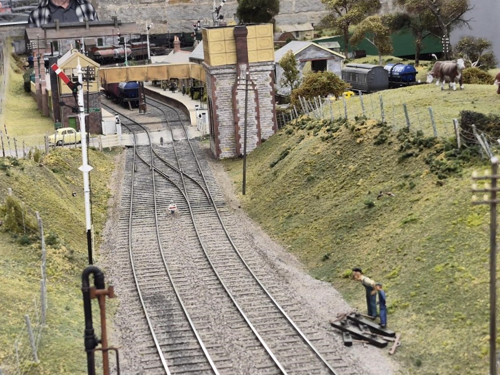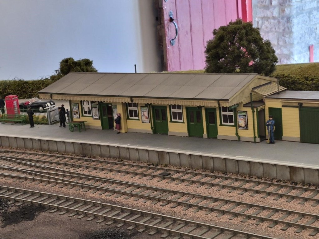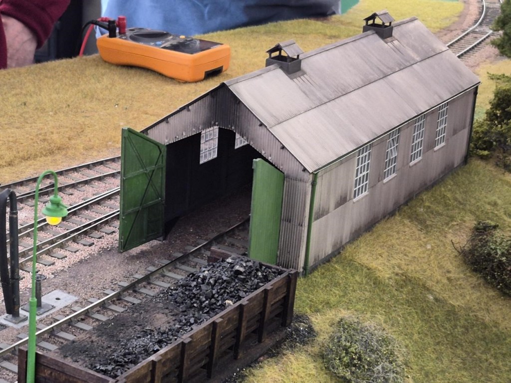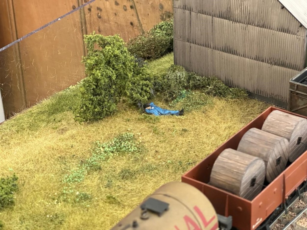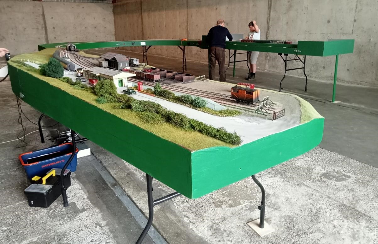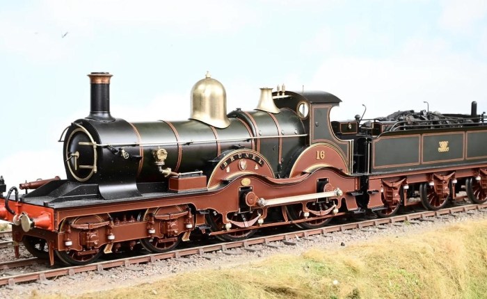
David’s Open Day in April featured both Nethercreech Junction and his new creation Lyme Regis. Some photos taken by YMRG members of Nethercreech Junction follow:
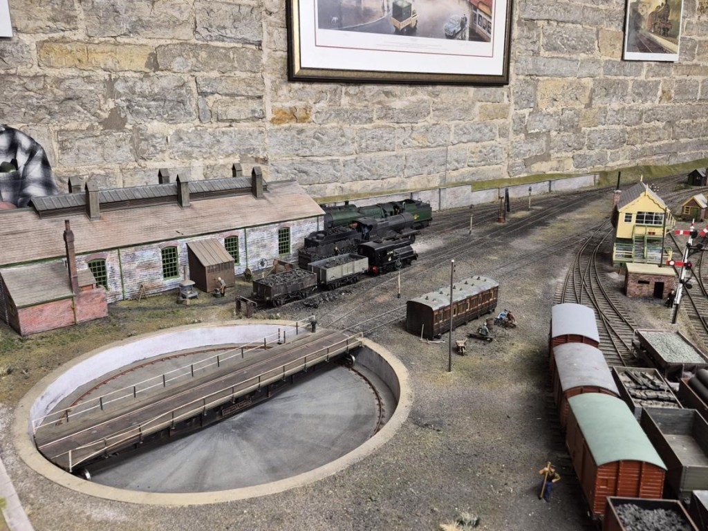
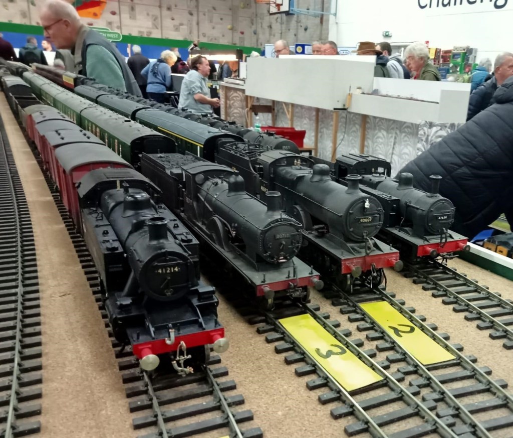
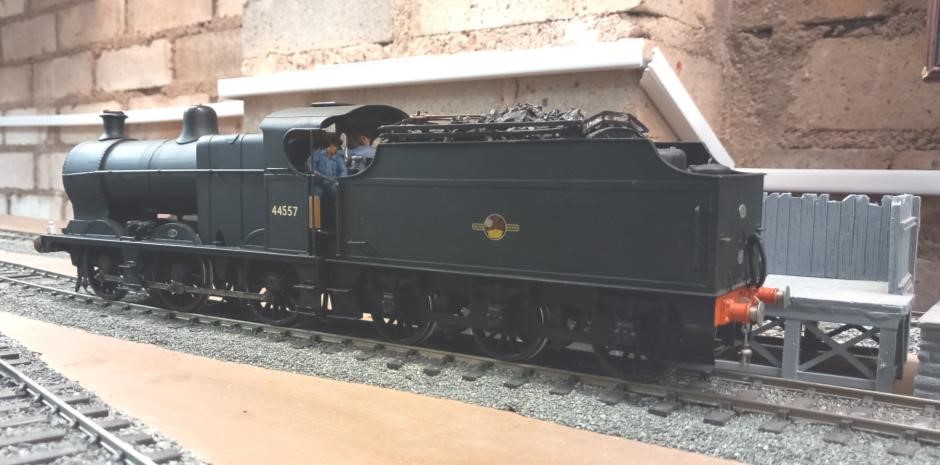
NetherCreech Junction Loco Depot
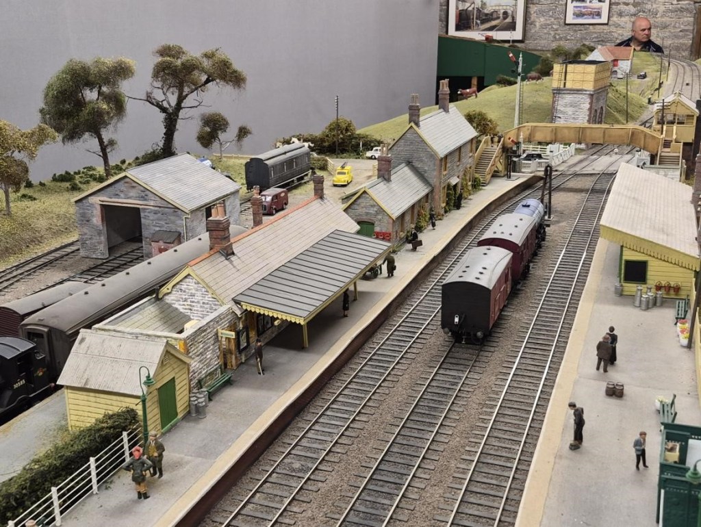
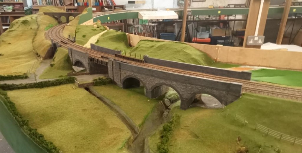
NetherCreech Junction Looking South
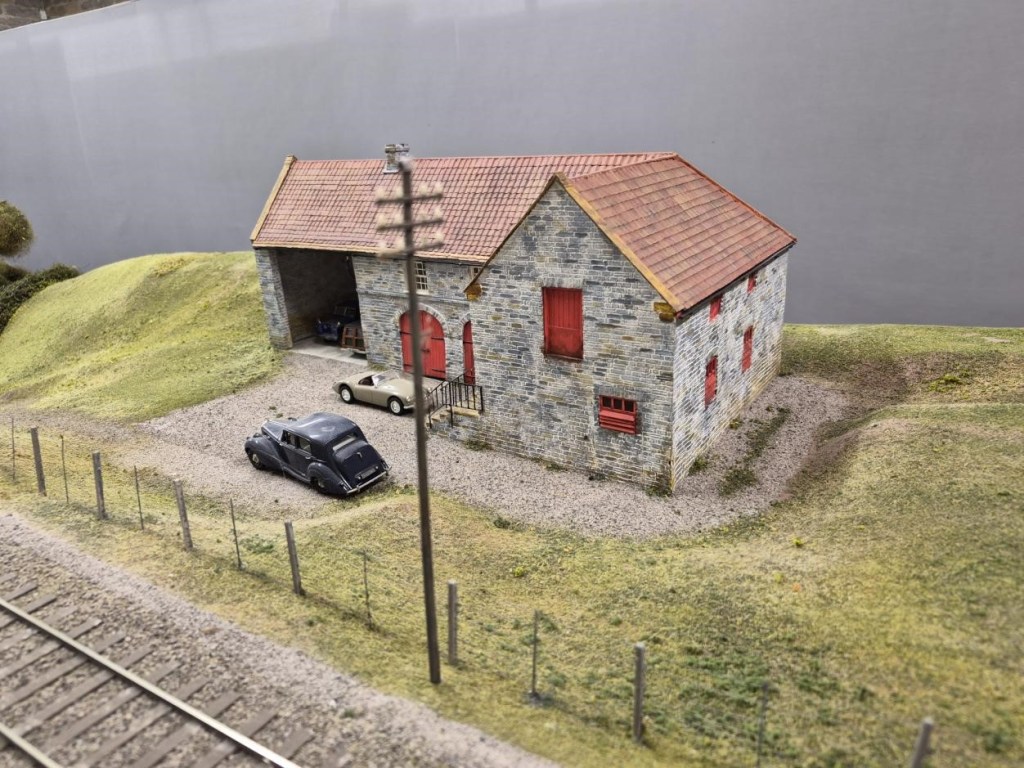
A Model of the Barn that Houses Nethercreech Junction and Lyme Regis painted in Estate Colours with Ivo Peters’ Bentley outside – as it really was on the Open Day!
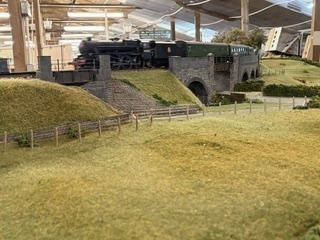
Looking North towards the Level Crossing
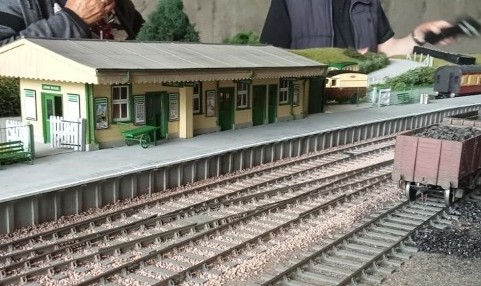
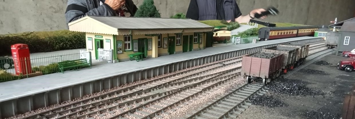
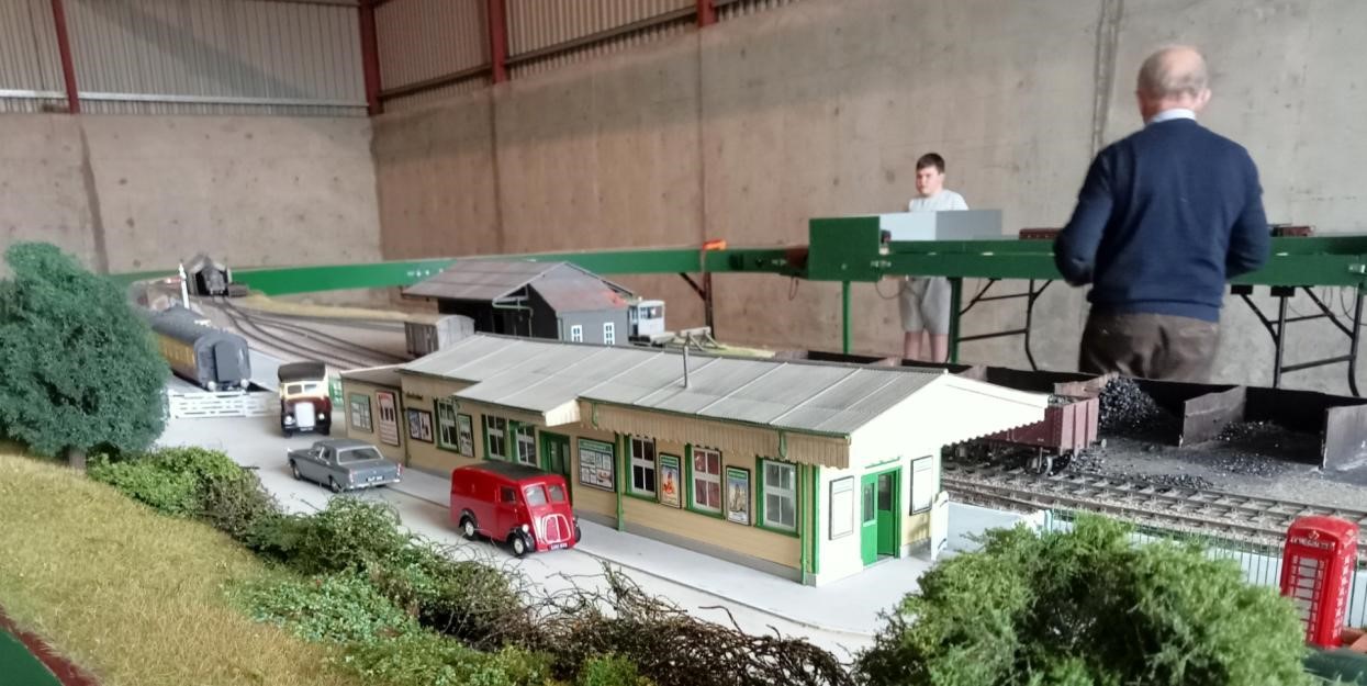
And now two views of Lyme Regis. Member and retired architect Allan has been responsible for the buildings and excellent renditions they are too:
Finally, two further cameos at Lyme Regis:
Looks like a nice place for a snooze.
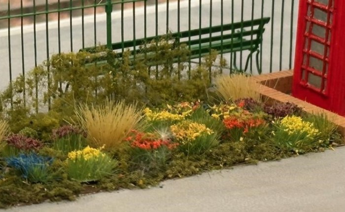
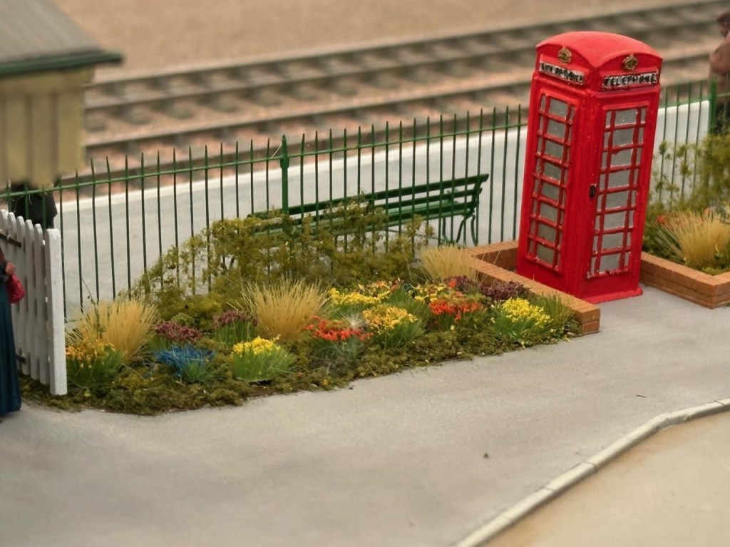
Is this the best flower bed on any layout in any scale anywhere?
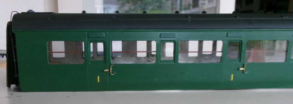
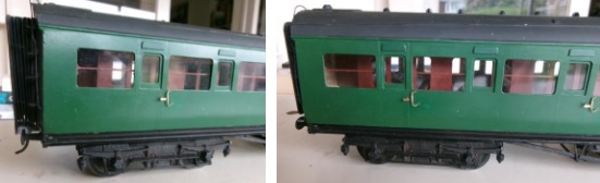
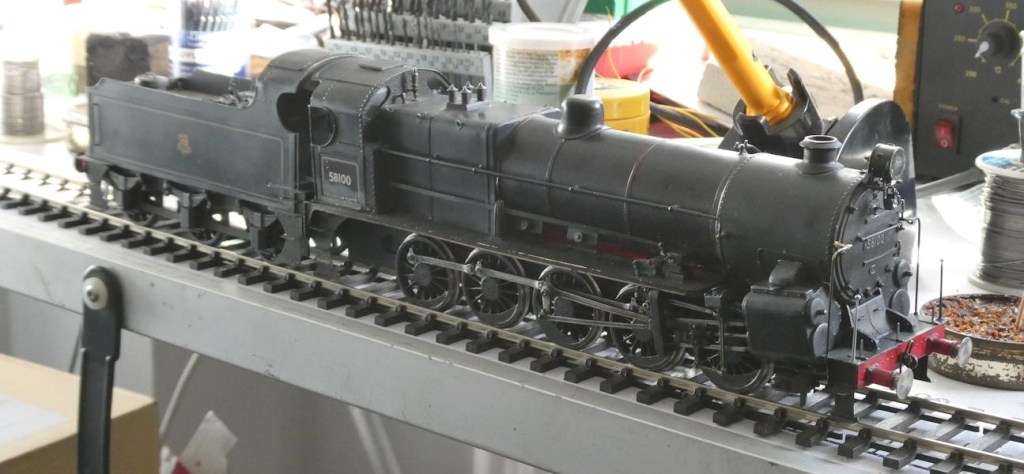
Pete C reports: The Maunsell coaches that the club bought from the estate of Simon K have had a few modifications and some repairs, one being a new bufferhead which had fallen off from a whitemetal buffer. A piece of brass was filed to shape and a spigot soldered in a hole in the buffer head to attach to the whitemetal housing. He then noticed that the cowling over the droplight windows had never been fitted, these were cut from plasticard and painted (luckily Railmatch paint was the same shade) then stuck on with thin superglue. The other noticeable missing items were the very prominent wooden handrails behind the corridor windows. Copper wire was painted and fitted to clips made from plasticard. The remaining job is to drill some holes in the solebar to secure the footboards properly.
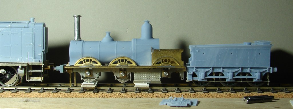
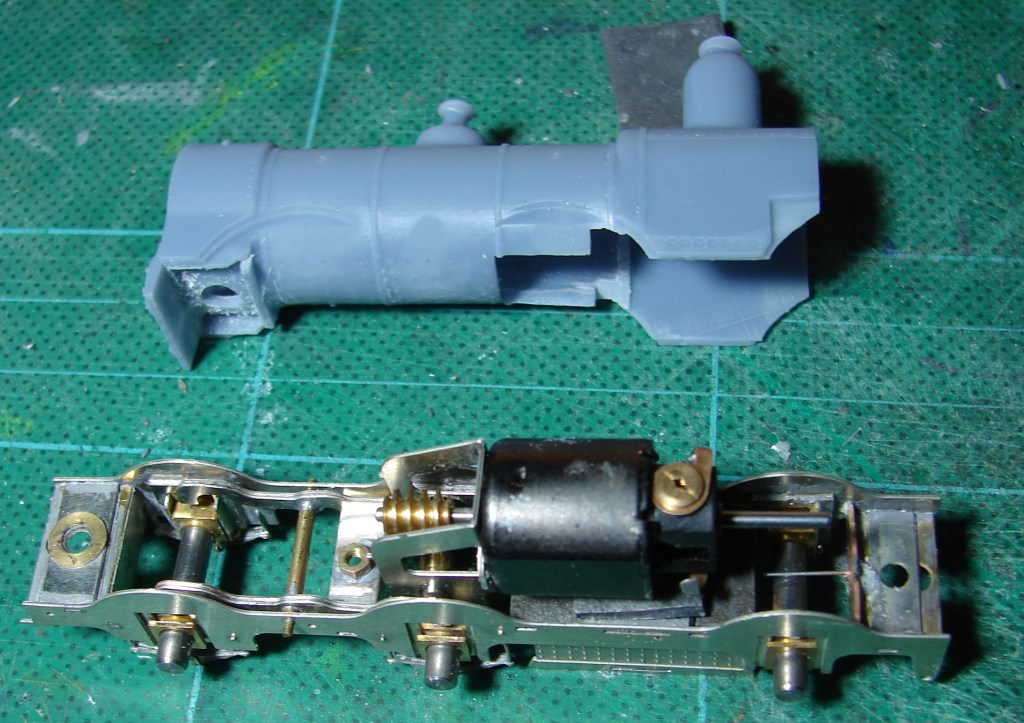
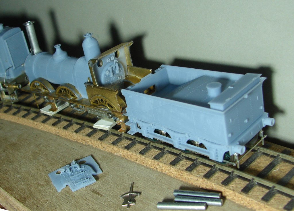
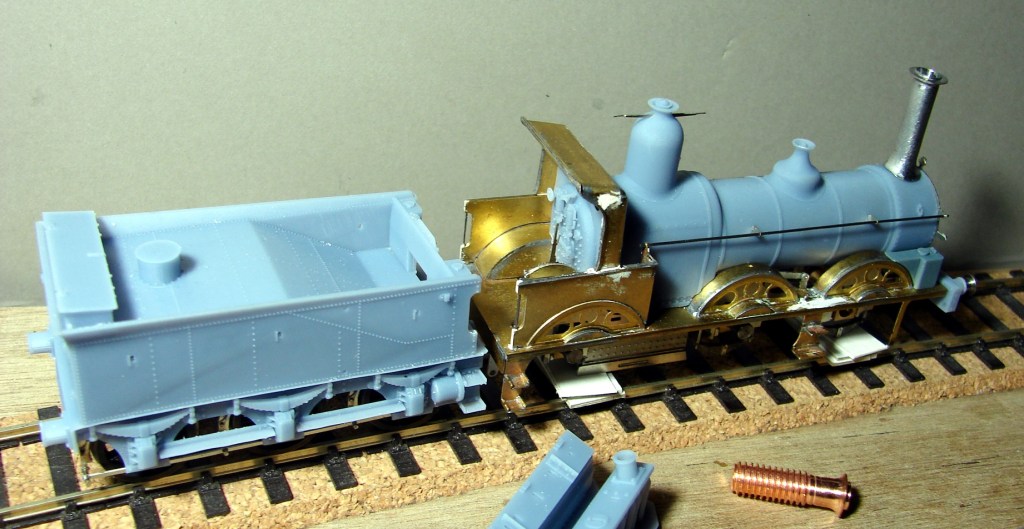
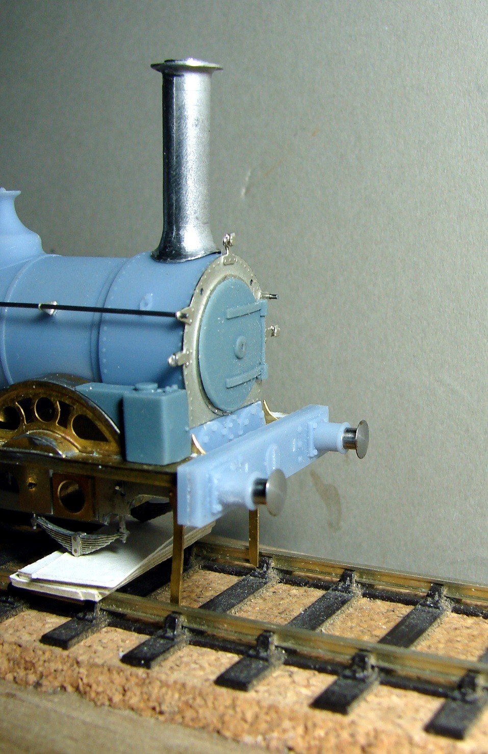
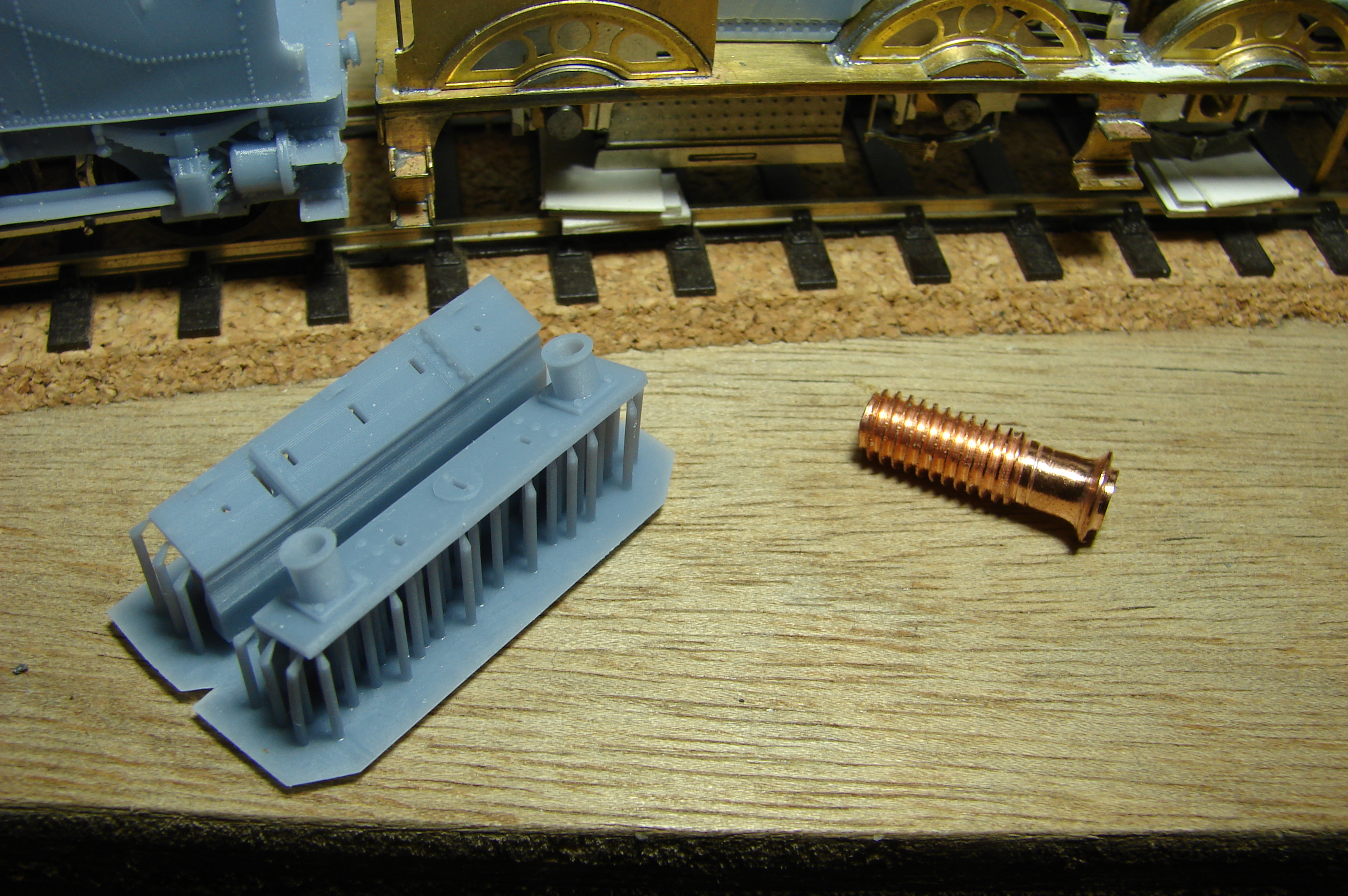
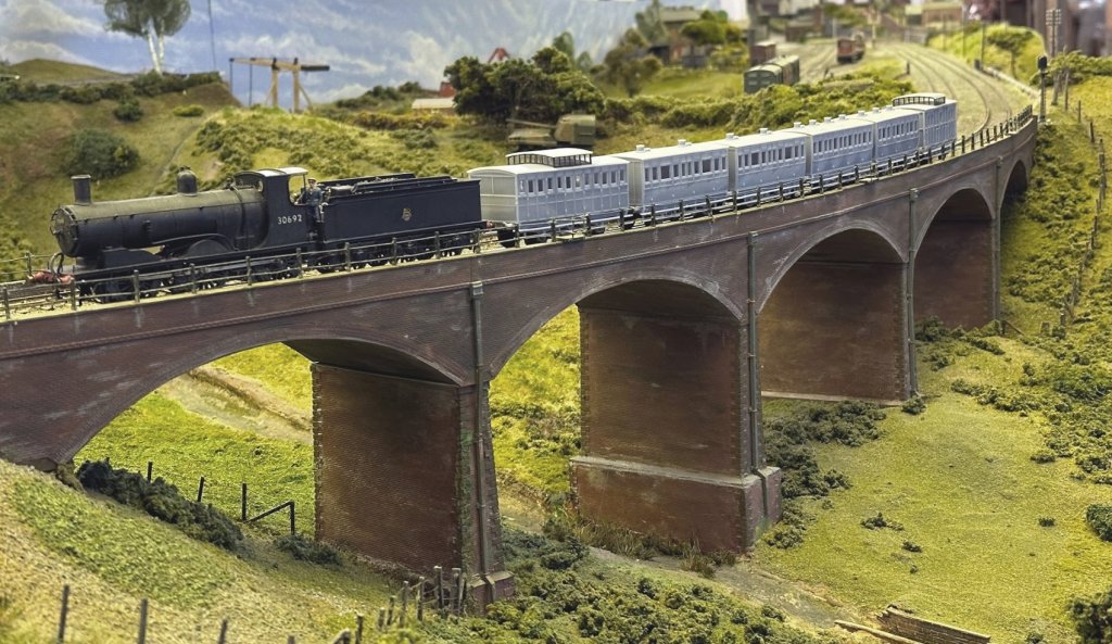
Steve has been steadily working through the many issues of 3D printing his LSWR coaches from the 1860s (in 4mm scale EM Gauge). Courtesy of Keith, not the Downton Train Crash formation of 1884, but a very close coupled rake of 3D printed coaches of all the required types crossing Bob Alderman’s viaduct on South Junction. The 1864 Passenger Brake is leading two 1865 Thirds, an 1862 Second and 1862 First, with the 1859 Passenger Brake bringing up the rear.
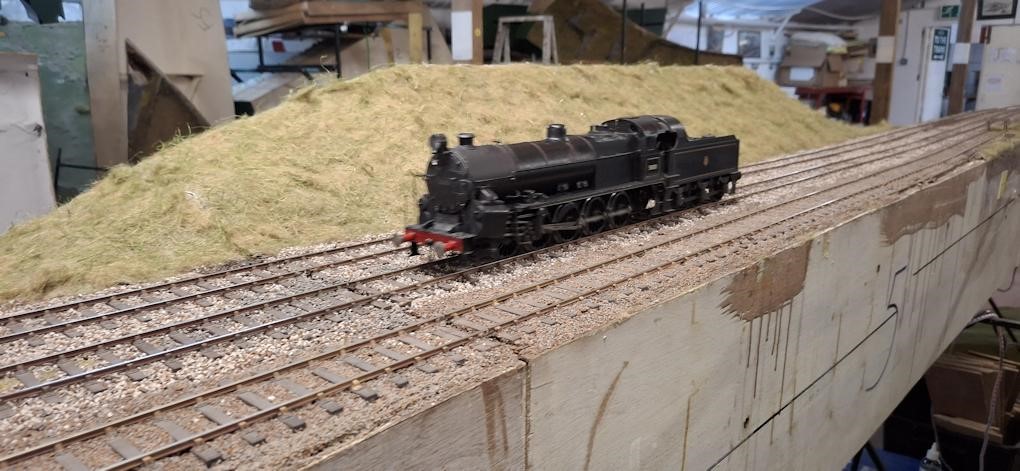
The Black Motor 30692 is the least inappropriate engine that he currently has to haul them, although it is at least a Sal&D engine. Built from a Jidenco kit by someone who had some idea of what they were doing and bought secondhand. The somewhat undercooked Jidenco 00 Gauge underpinnings were replaced using Persy chassis kits built to EM Gauge. Those familiar with Steve’s projects will guess that this could be made more complicated than it really needed to be: https://yeovilmrg.org/black-motor-re-chassis-in-em-gauge/
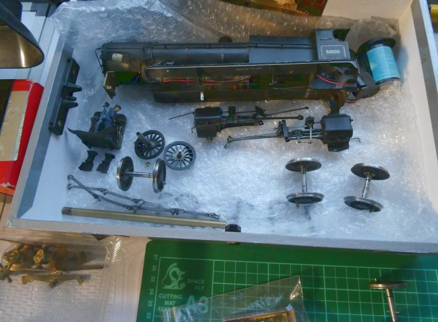
Finally Part 2 of the Big Bertha saga that could be a trilogy if it includes fitting the brake gear.
Jim has concluded that CS2 is not the best place to try and make something of the ‘Aberdeen White Elephant’, otherwise known as the ginormous 2mm finescale fiddle yard that I carted down from its namesake in north east Scotland (ie Aberdeen!) in the summer of 2019 and done little with since, due to (a) Covid and (b) his house move to Exeter in 2022.
Despite the loft in his bungalow having insufficient headroom to stand up in, and the loft hatch being unable to accommodate 8ft long baseboards, he has decided that he can make a better fist of it there than he first thought, and it will remove the need for regular 100 mile return trips back to Somerset.
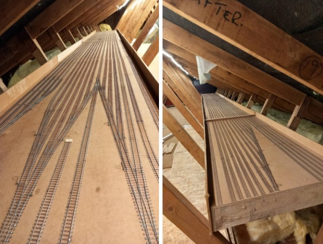
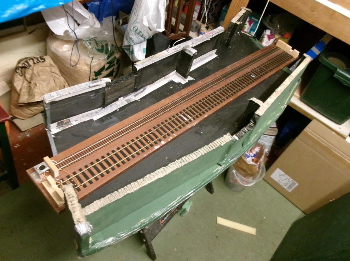
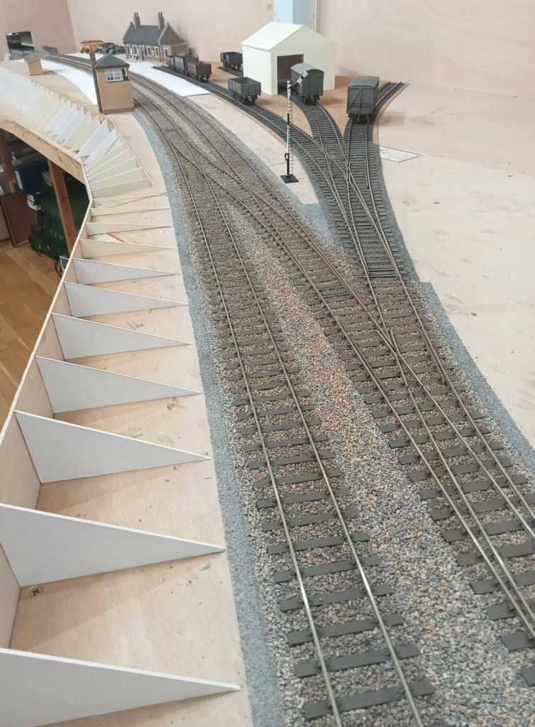
Accordingly, he ‘bit the bullet’ a few weeks ago and carefully cut a few millimetres out of all the rails (36 at every baseboard joint with 18 parallel storage roads) followed by gently sawing through the MDF baseboard top to convert three baseboards 8ft long into six baseboards 4ft long. All six boards are now up the loft at home and, simultaneously, I am adding raised flooring to gain access right down the length of one leg of the roof space. Below is a picture showing four of the boards, with two more to be added at the far end, before a corner is added:
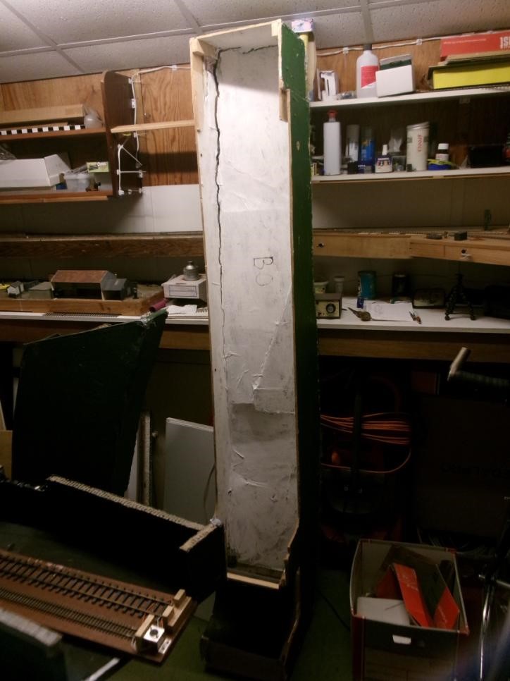
The second picture is taken from the other end and shows the fifth “half-board” added and more of the new flooring to the left. Of note is the relatively little vertical leeway Jim has to insert cross struts to support the boards more positively.
In May, the 2mm Scale Association is having its usual show at the Derby Conference Centre and this year it is all weekend, rather than just Saturday, and the star of the show will be Dunallander, which this fiddle yard was originally built for. Included in the van from Aberdeen this time will be the Perspex sheets that cover the fiddle yard boards which Jim forgot to collect in 2019!
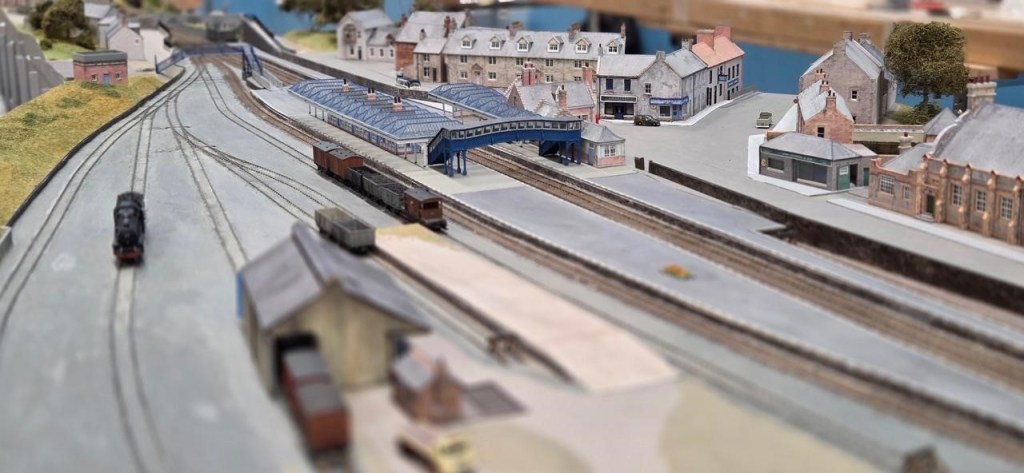
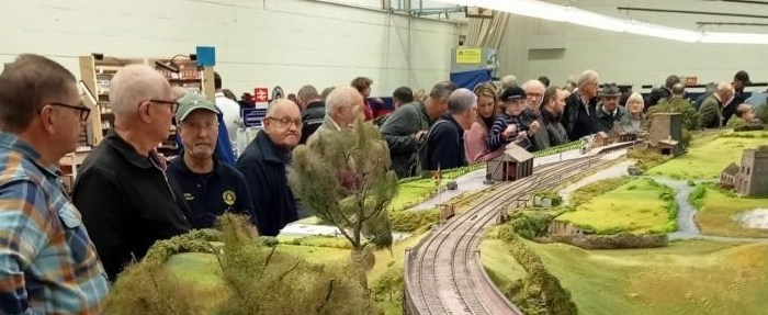
A reminder that the scenic side of the layout has yet to be started but, in comparison, will be very simple and comprise a double track main line, with overhead 25kv catenary (!) and mineral exchange sidings and a branch leading to Littleton Colliery, near Cannock in Staffordshire. In contrast, the Grampian Area Group of the 2mm Scale Association, who was persuaded to save the scenic side of the original layout, have strived to construct an almost exact copy of Dunblane Station and its immediate environs, involving many, many buildings – see photo above at the Elgin Show. In contrast Jim’s rendition of Bungham Lane, Penkridge only needs one building, the junction signal box!
February saw Part 1 of the Big Bertha Repair ending on a cliff hanger see the link below:
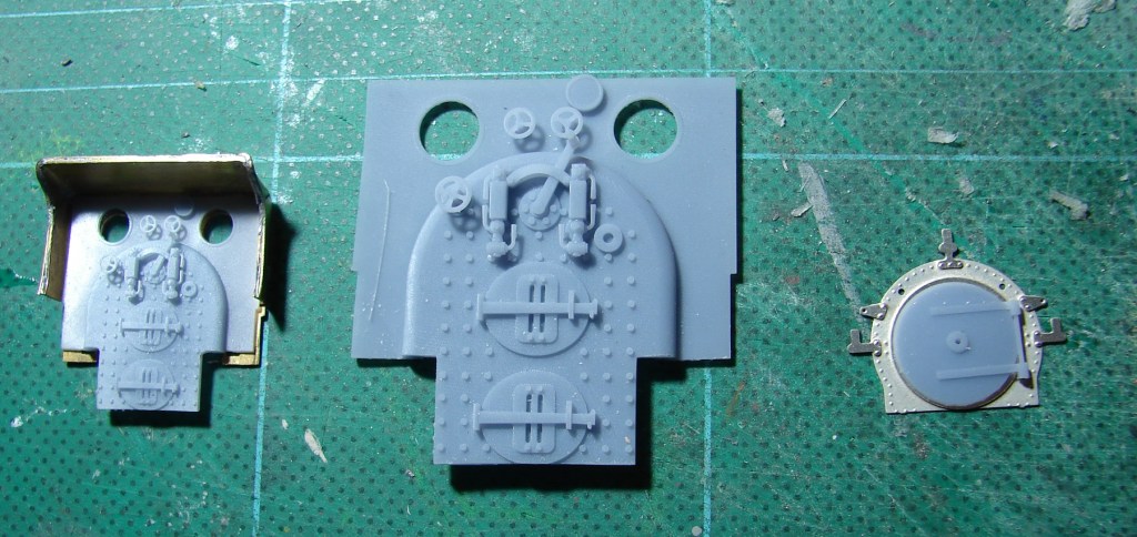
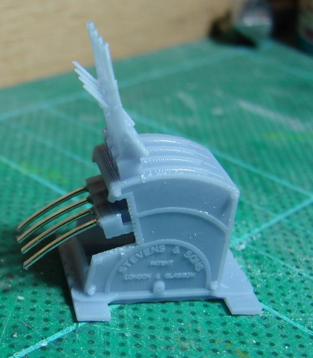
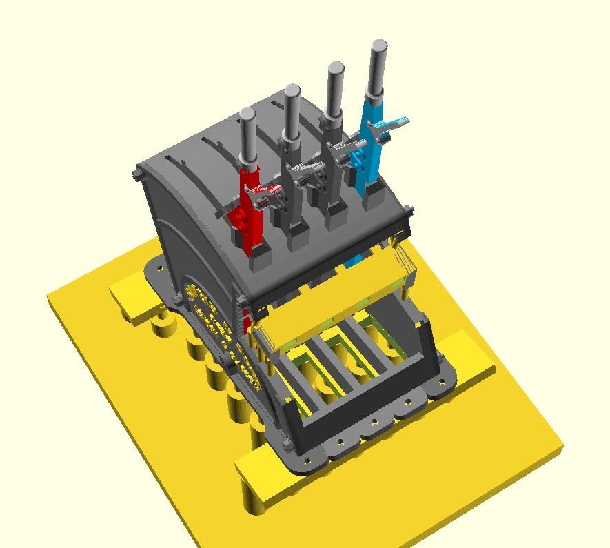
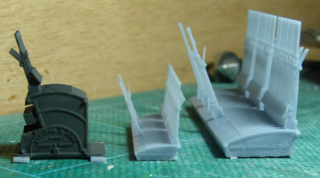
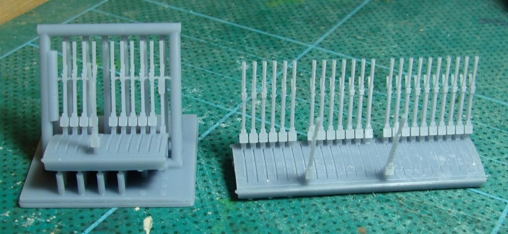
Steve is modelling Verwood in EM Gauge, and needed a Stevens style lever frame for the box plus a Stevens style Knee frame for the ground frame that was at the West Moors end of the loop. He’s 3D modelled these in QCAD and OpenSCAD and is 3D printing them in 4mm and 7mm scale on his AnyCubic Photon Mono 4K in AnyCubic ABS-Like Water Washable Resin 3.0. Both can be configured to have LSWR or SR style plates and with any number of levers. Could the models be 3D printed though?
This is a 7mm scale version of Steve’s 3D printed LSWR style ground frame for Verwood with some overly thick tails fitted to the locking frame. The clearness of the text suggests to Steve that his BR(S) smokebox plates (with curly 6s and 9s) could probably be printed vertically rather than on the bed allowing me to batch them up on a raft and remove and prepare them as required.
A test print showed that when tilted up on supports for 3D printing, the void under the tails needed to be more realisticly modelled (almost empty bar framing) so that it could drain of resin and water during washing. Win-win!
On the left a reject ground frame with coat of Humbrol Dark Grey to bring it to life. Also ‘Privett’ LSWR era frames in 4mm and 7mm scale with just the FPL levers reversed, as these frames were for most of the day waiting for something to happen. These sort of frames were not untypical of the Meon Valley and other somewhat overbuilt lines of the same period.
On the left a lever frame for Verwood in the final version of the support cradle. As with the ‘Privett’ frame on the right, what should have been the only FPL is pulled awaiting the next train – that was a mistake as it should have been Lever 4! The Privett frame was fairly easy to release from the final version of the support cradle with nicely aligned levers. It looks like some of the supports for the Verwood frame went AWOL but recovered just in time! There were a lot of iterations of the support cradle before it worked reliably every time.
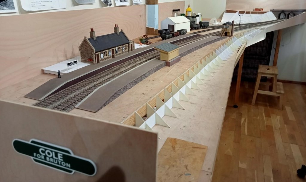
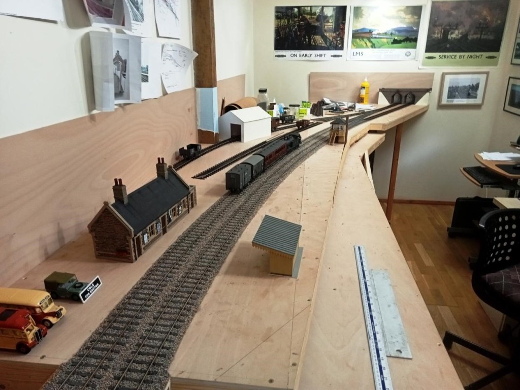
Allan is making good progress on his 7mm rendition of Cole. Platforms have been started and landscape formwork started. The platform surface was finished using fairly fine emery paper dusted with weathering powders (and brushed off outside as the stuff gets everywhere!).
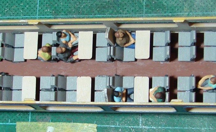
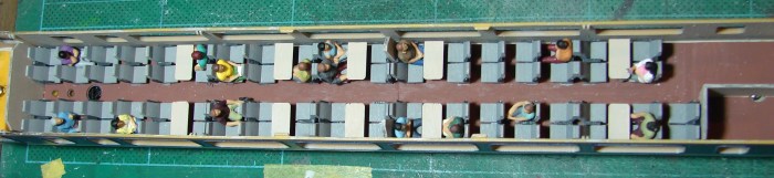
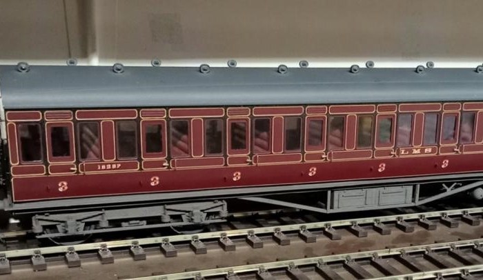
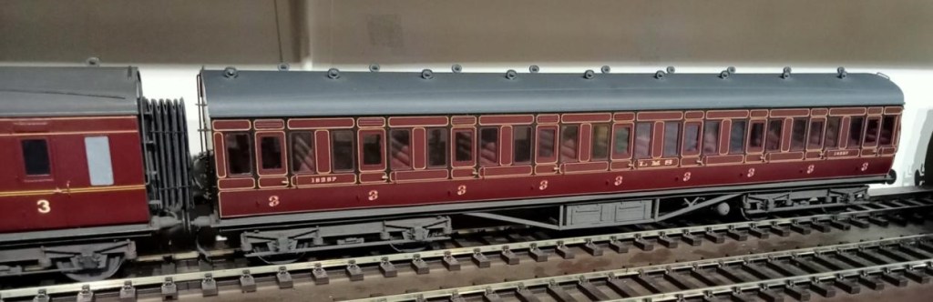
This is a recently acquired LMS Period 1 all third coach built and painted by the Sidelines man himself Malcolm Binns. Jim couldn’t resist it even though outside his period as the lining is outstanding. Unfortunately Jim had to refix the seating and entirely reglaze it – old model, old glue!
Plan of Proposed Layout
Andrew has been busy planning and ordering parts for his O gauge layout Crucaern Station (Anglo Saxon for Crewkerne. “Cruc” is hill and “aern” is a place or building). He’s taken delivery of a large box of points and track from DCC Train Automation.
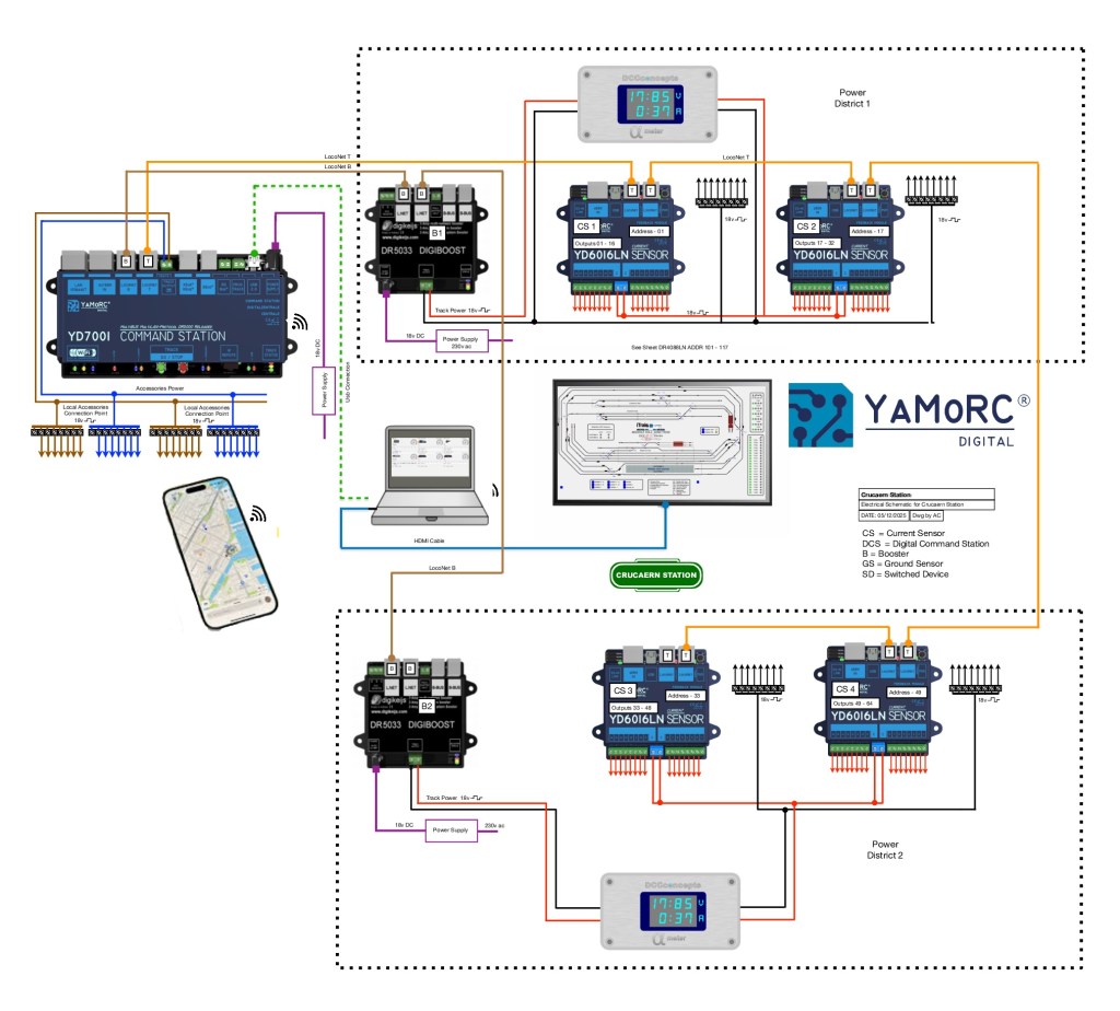
iTrains Control System Diagram
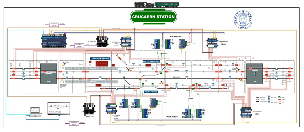
iTrains Schematic showing where everything needs to go
Below a few words to describe what should happen.
System Description for Crucaern Station O Gauge Layout The control system for the Crucaern Station layout is built around the YaMoRC YD7001 command station, which provides the DCC command signal, LocoNet communication, and accessory power for the layout. The layout is divided into two electrically isolated track power districts to improve reliability and fault handling. Each power district is supplied by its own DR5033 booster.
Track Power Distribution Track power within each district is delivered via dedicated red and black wiring from the DR5033 boosters. The two power districts are electrically independent, allowing one district to continue operating if the other experiences a short circuit.
Booster Communication (LocoNet-B) The boosters receive their synchronised DCC control signals from the YD7001 via brown LocoNet-B cables. These connections ensure all boosters operate consistently and maintain a stable DCC output across the layout.
LocoNet Communication Network A network of orange LocoNet cables interconnects the command station, feedback modules, boosters, and display units. This network carries system-wide communication including block occupancy data, device status, and accessory control.
Block Detection and Feedback Each district includes a combination of DR4088LN-CS and YD6016LN feedback modules. These units provide current-sensing and ground-sensing block detection, reporting the presence of trains to the control software via LocoNet. This enables automated operation, route setting, and visualisation on the layout mimic panel.
Accessory Power Accessory devices such as point motors, relays, and signals are powered using a separate accessory DCC feed from the YD7001. This keeps turnout and accessory operation independent from the track power feeds to ensure stable running.
Power Meter Displays Digital display units within each power district monitor voltage and current draw in real time. This provides clear visual status information for operators and helps diagnose faults quickly.
Control Interfaces The YD7001 connects to a computer for layout control software and to wireless devices such as smartphones and tablets for handheld throttle operation. A screen-based mimic panel provides a graphical overview of the entire track plan, including live block occupancy and turnout positions.
Technical Overview This layout is divided into two power districts, each managed and monitored to provide reliable DCC operation, feedback reporting and accessory control. The wiring scheme uses a combination of power buses, boosters, feedback modules, point motor drivers and signalling components, all coordinated through the YD7001 command station and LocoNet.
Power Distribution A pair of red and black solid lines represents the main DCC track bus. This bus supplies traction power to the entire layout. The bus is divided into two separate power districts, each protected and managed independently. Dotted boundary lines identify the equipment assigned to each district.
Boosters and Command Station The YD7001 acts as the central DCC command station. It provides: – Booster outputs (brown lines) feeding the DR5033 boosters via LocoNet B. Each DR5033 supplies regulated track power to its respective power district and provides short-circuit protection. – Auxiliary power outputs (blue and brown lines) used to feed point motors, accessory decoders and other low-current devices.
LocoNet Communication All digital communication between devices is carried by orange LocoNet cables, linking the YD7001, boosters, feedback modules and accessory controllers into a unified network. This ensures reliable synchronisation of power management, occupancy detection and signal control across the entire layout.
Block Detection and Feedback The track is divided into several blocks, each identified by blue labels. Every block contains two feedback sensors, represented by red labels, providing precise occupancy detection. These sensors report directly to the feedback modules via LocoNet, enabling automated signalling, route setting and train monitoring.
Points and Signals Turnout control is handled through green-labelled point motors, each connected to the accessory power bus and controlled via LocoNet accessory commands. Yellow-labelled signals are positioned at block boundaries or key junctions. They respond to feedback events and route logic, ensuring accurate line-side indications for both manual and automated running.
Overall System Function All components operate together as a coordinated digital layout control system: – The YD7001 provides command, logic and accessory control. – The DR5033 boosters supply isolated, protected traction power. – Feedback sensors deliver block-level occupancy data for automation. Accessory devices such as points and signals respond intelligently to LocoNet instructions. – LocoNet interconnects the entire system, maintaining consistent communication. The result is a fully integrated DCC control environment supporting automated operations, realistic signalling and reliable running across the layout.
Andrew also informs us that there are only two boards left of Heyno Junction to wire up before trains can run complete circuits! [Ed. Something I can understand!]
For the last few months most of the work at CS2 has revolved around getting Evercreech New ready for its second appearance at Taunton Railex. Happily its appearance was an outstanding success and the team involved should feel very proud and pleased, especially given the hard work involved. The Somerset Railway Modellers were brilliant hosts and Taunton School a superb venue with proper puddings. A few pictures from the event follow:
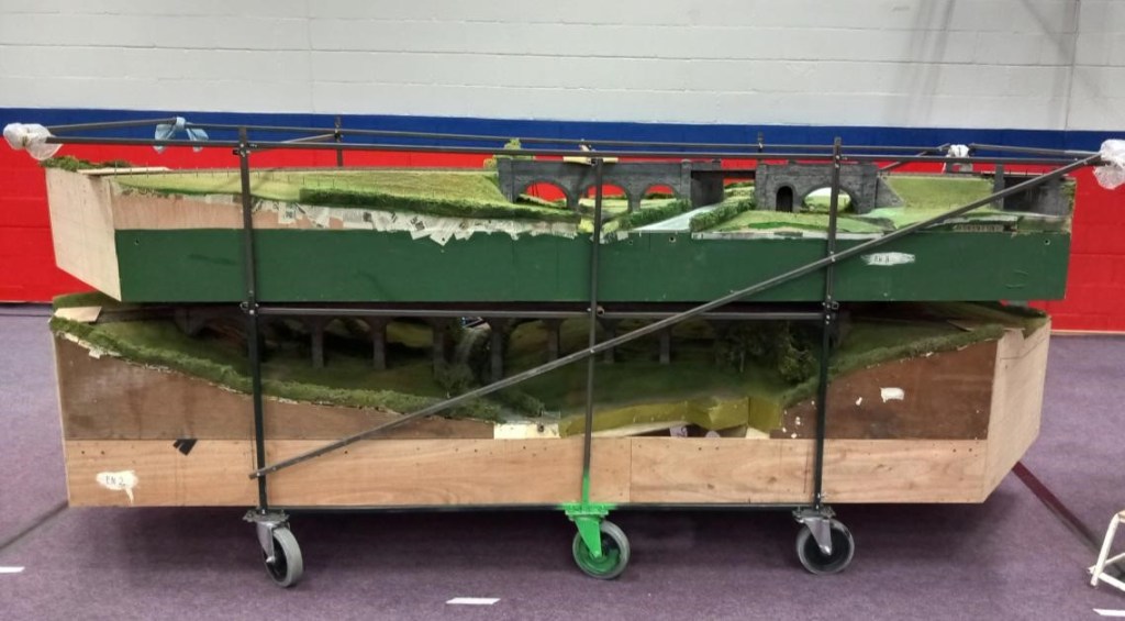
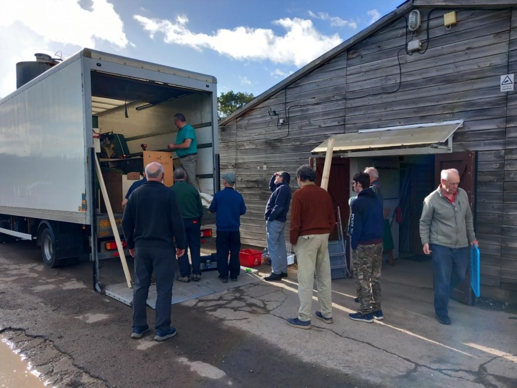
The infamous viaduct stillage (when loaded the size of a small car), with Prestleigh Viaduct on the bottom and Pecking Mill above. The castor painted green is key to the loading procedure – there are actually six castors on the stillage, and it has to be carefully pivoted on the outside edge of the tailboard on the green castor since the stillage is too wide to go in sideways.
This is why we do this!
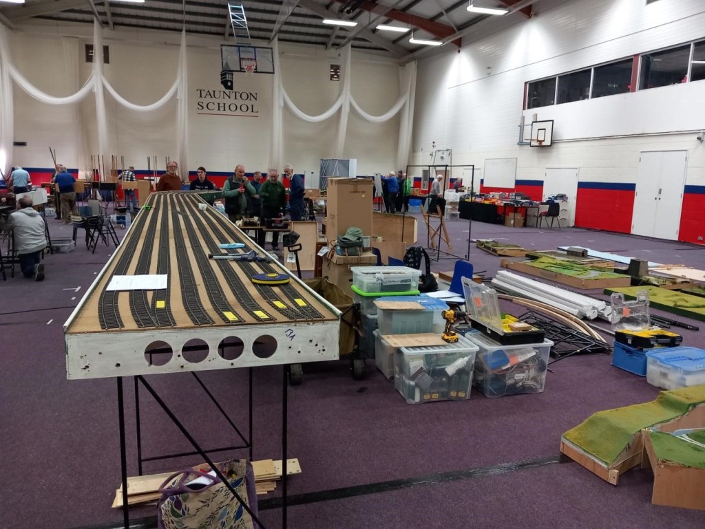
The fiddle yard, with the operating area of other layouts behind.
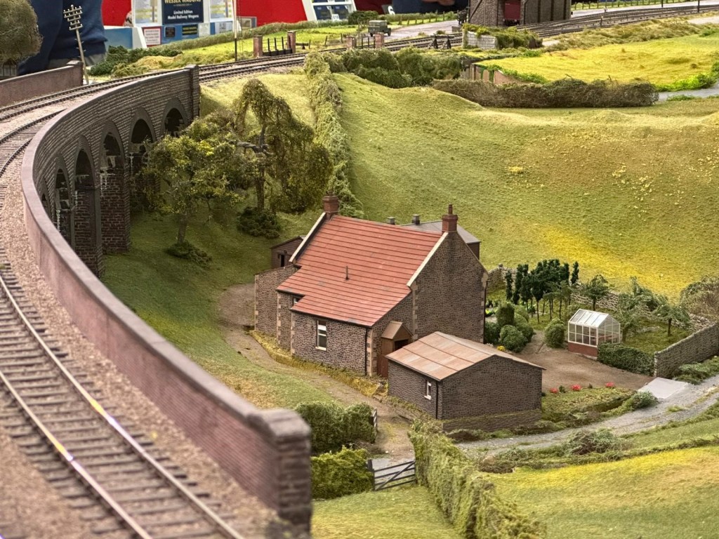
Prestleigh Farm, which is unfortunately mainly hidden from the viewers by the viaduct, although Dave H constructed a high level background mirror to help with this. Next a few pictures taken during loading at CS2 and unloading at Taunton School:
With more scenery than last time, will it all fit in the lorry? Maybe……
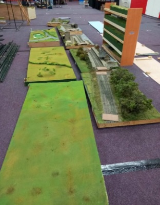
The the new landscape boards (left) and original station boards waiting to be loaded.
Early stages of setting up on the Friday with a good three hours to go before it will be ‘ready to run’.
Meanwhile, In his large purpose built railway shed Allan has been working away at his new project, Cole (S&D) in 7mm Scale. The trackwork has been constructed from C&L components on plastic sleepers and the three way point was ‘particularly challenging’. [Ed. The ballast and colour of the sleepers I find pretty convincing, and doesn’t it flow nicely.]
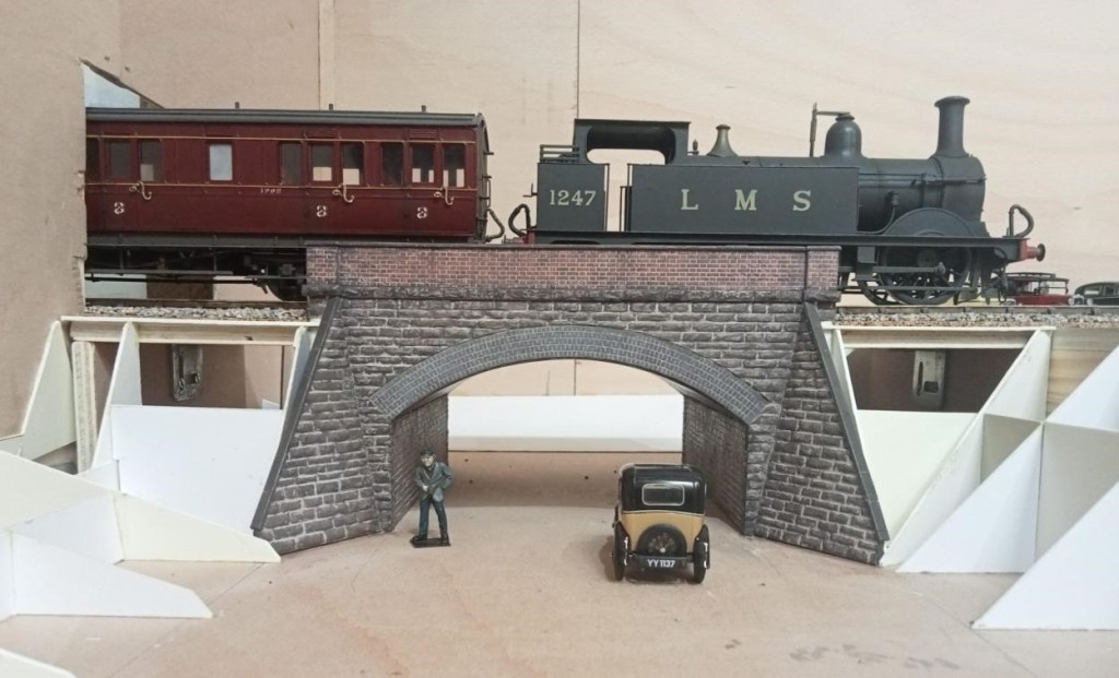
The bridge over the lane going up to Sunny Hill School. Will the Austin 7 need to reverse to make it up there? The arch was laser etched and cut by Mike of Jurassic Models.
The project that has gripped Jim over this period was improving an ex-LMS 4F 0-6-0 which he bought some while ago via the Gauge O Guild ‘Sales and Wants’ on its website. A kit of some description, it had been constructed in true ‘Tri-ang fashion’, with the motor/gearbox installed horizontally so the lower part of the boiler had to be removed. Jim managed to re-install this with the motor sited vertically in the firebox some while ago, but he has now got around to filling in the missing part of the boiler and remodelling the inside of the cab so a crew could be added. A false floor was constructed out of plastic card to match the level of the tender and a flap of very thin plastic card added to bridge the gap. Hopefully the crew won’t now fall out!
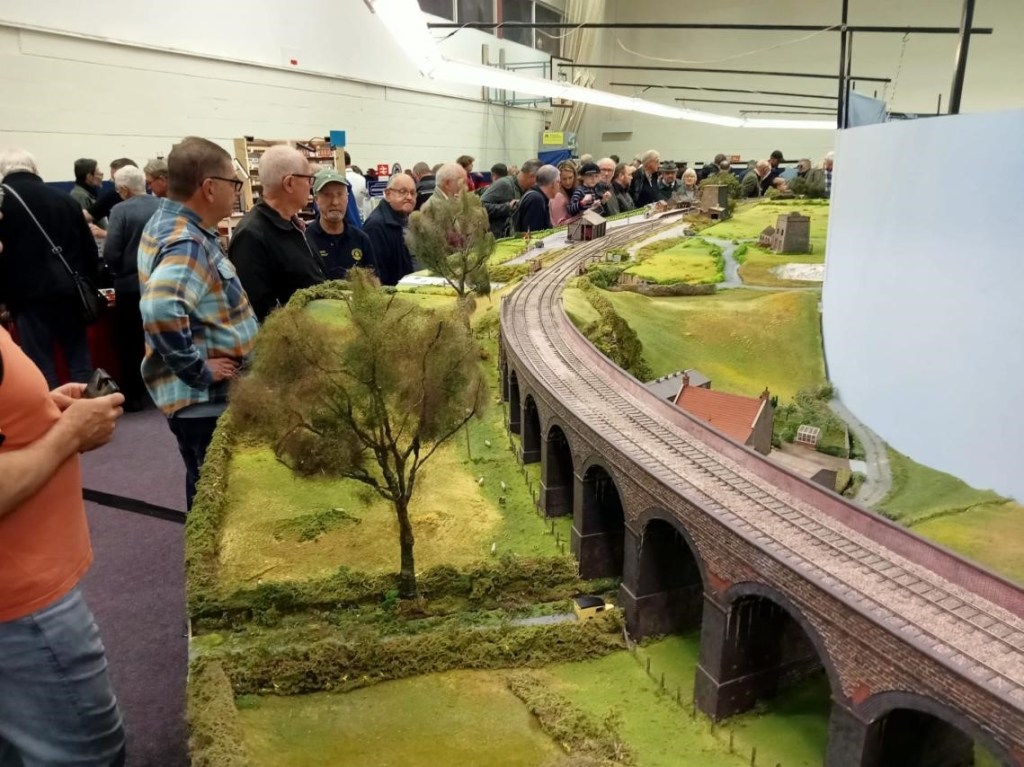
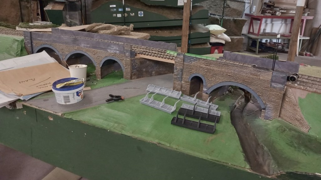
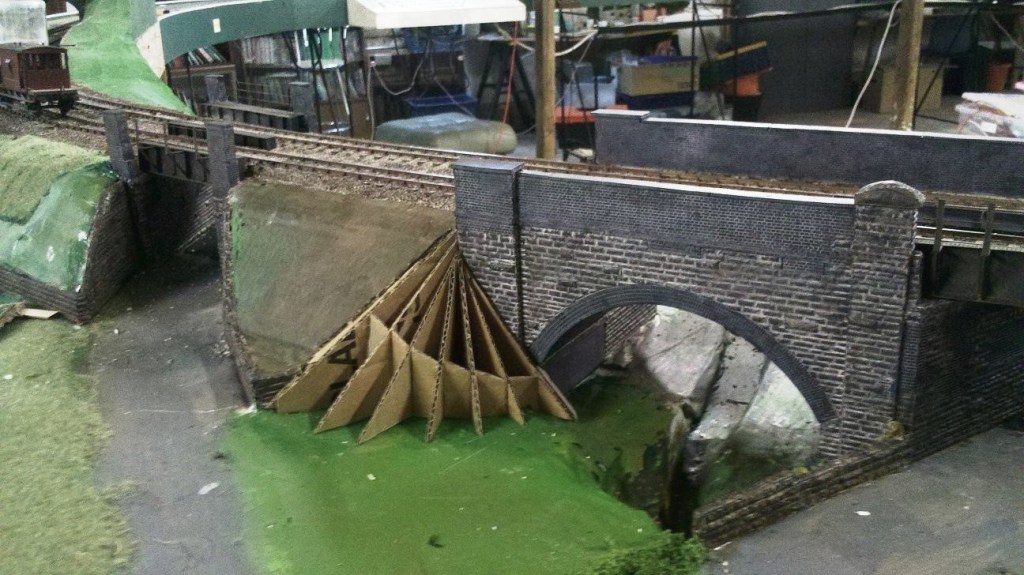
The main efforts in CS2 have been directed towards developing the scenery on Evercreech New ready for its appearance at ‘Rail-Ex Taunton’ in late October. At a recent visit to CS2, Allan took some pictures of the area around the two viaducts. As can be seen things have really started to come together on Evercreech New.
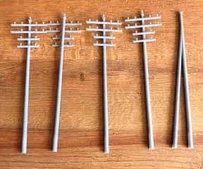
New bridge sections have arrived, made in a flexible ABS-like resin. They’re much easier to fit and are currently on the workbench getting some weathering treatment to help them blend in nicely. Over on the Pecking Mill Viaduct, the scenic team has been busy with the static grass, and the area is really starting to look the part. Fences and hedges have gone in too; which adds a lot of depth and character. Some very neat 3D-printed telegraph poles have been made up. These are destined for both the Pecking Mill section and the station area, and will add another great detail once in place.
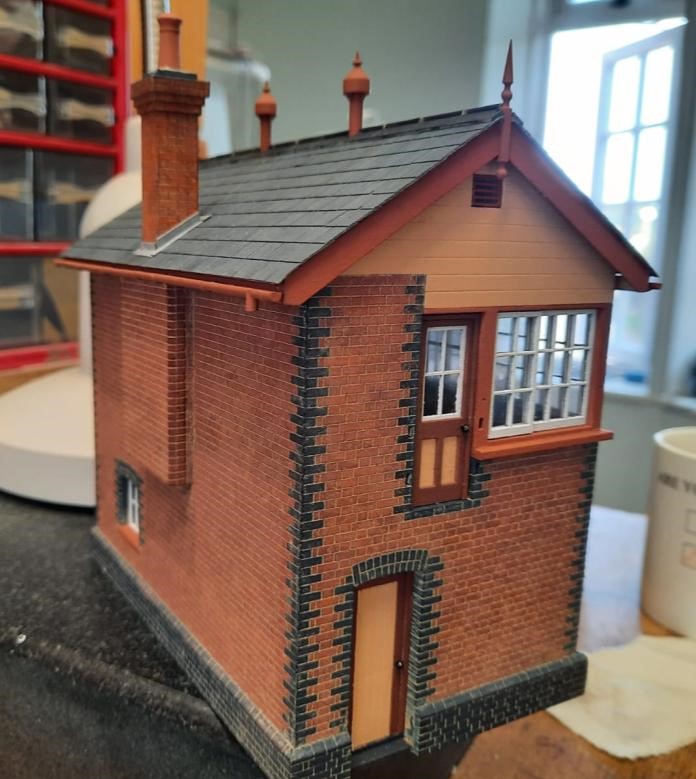
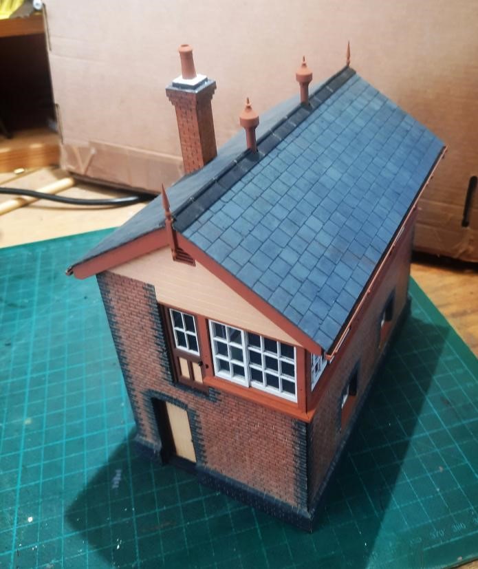
Dave H has been building a signal box from a laser-cut kit and now has the fun of the interior, using the etched brass kit from Severn Models
This reminded Jim of the signal box he had constructed some while ago for Littledean, from an LCut Creative kit, that included a full interior.
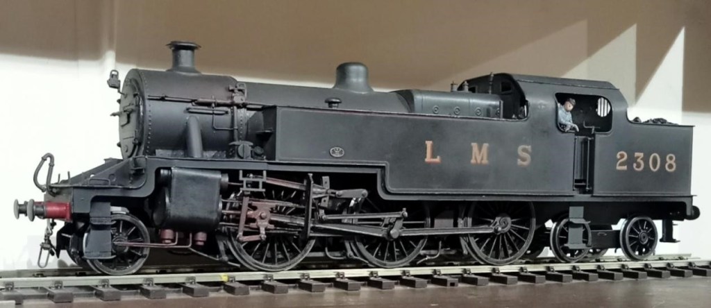
Allan has been beavering away at his 7mm rendition of Cole, and recently added an LMS 2-6-4T to his loco roster. Made from a Gladiator kit, the Fowler 4P has always been Allan’s favourite tank engine. He recalls seeing them in Manchester in his youth, but it is unlikely they ever appeared on the S&D. But what the hell it’s beautiful! [Ed. who wonders what that chimney is going to be when it grows up.]
This is where Cole stands currently. There will be a hole in the shed wall beyond the overbridge so that through trains can run on into the garden – not much point in modelling a through station otherwise. [Ed. 0 Gauge in the garden – where there’s room for it – what’s not to like?!]
Although not quite finished, in May David S held an Open Day to show his superb new 7mm layout of Lyme Regis in its entirety.
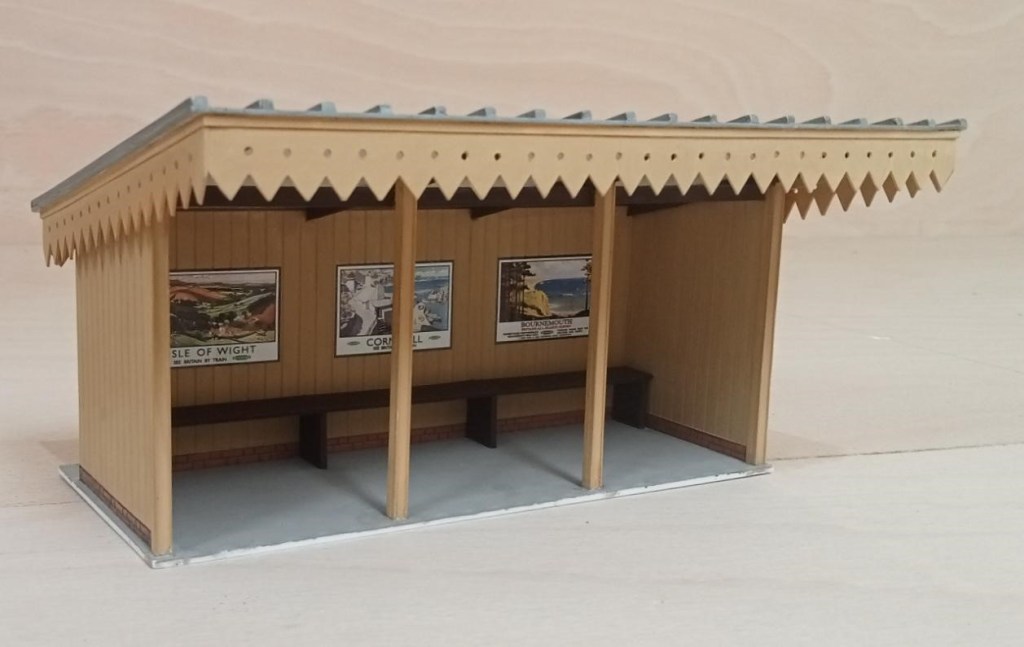
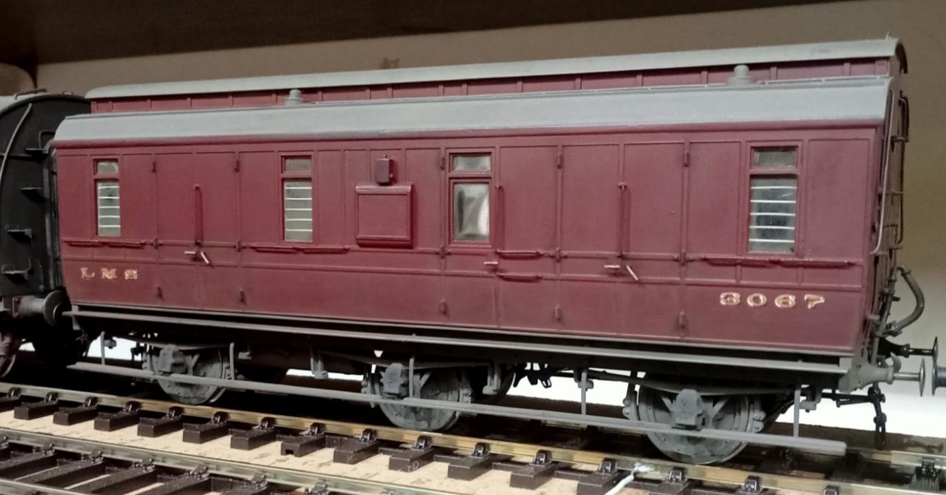
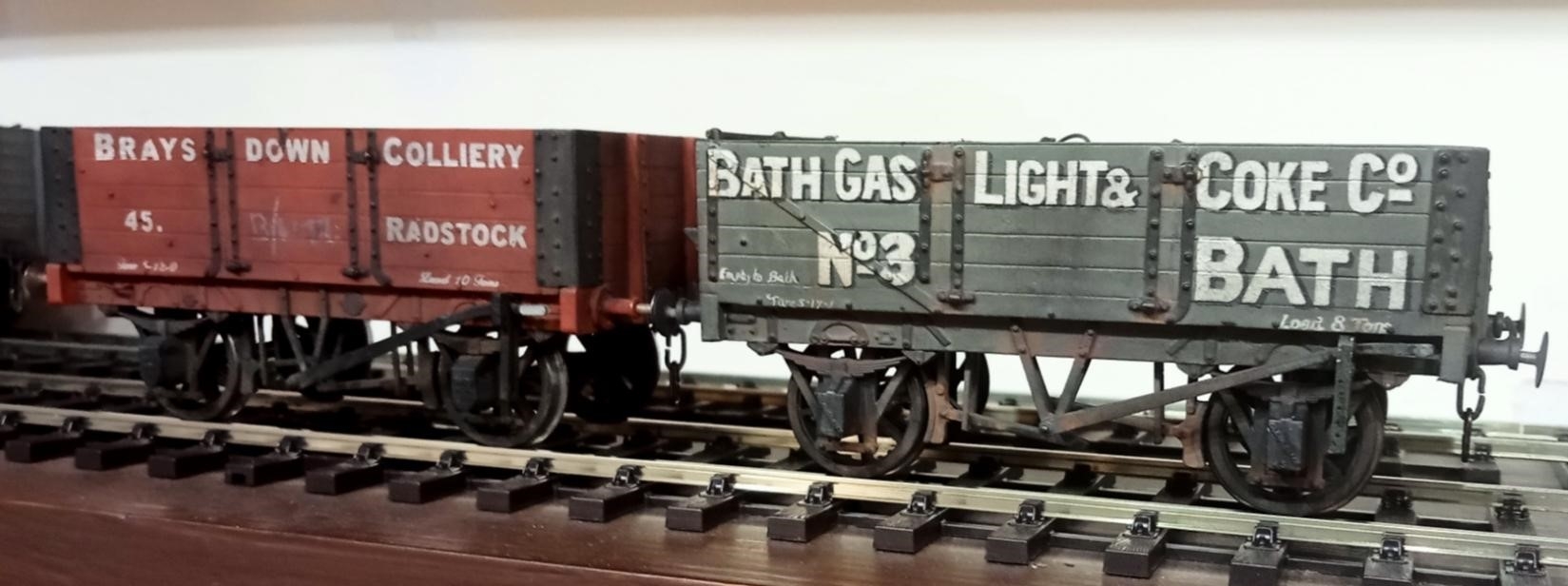
Alongside his work on Lyme Regis, Allan has continued work on his new 7mm layout and built the platform shelter for Cole (S&D) Station. Allan didn’t want to model the sag in the roof. Those props may well have been added to combat the sag on the real thing. Below is some additional rolling stock for Cole.
Since the last blog, The Summit has been exhibited at the two and a half day Bristol Show at Thornbury and acquitted itself well. Glimpsed in the background the scenic boards are back in their stillages and all hands have been diverted to Evercreech New which is due to appear at the Rail-Ex Taunton in late October.
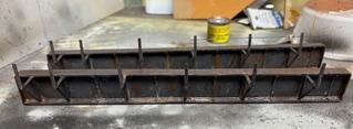
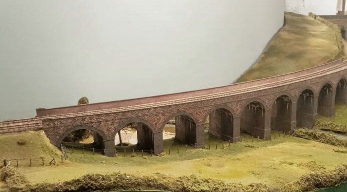
Pecking Mill Viaduct is a complex structure and a curve has had to be introduced to it so that it fits on our layout. Because of the curve the 3D printed girders for the skew bridges cannot be quite parallel or exactly the same length. All this has led to a potential lack of clearance if the girders are not precisely placed. There is a timber walkway outside the girder and the railings for those pretty much align with the outside of the piers leaving just enough clearance for model coach and loco overhangs. The girders may be very slightly outboard of where they should be as a result. The girders were printed in two halves, the farm bridge girders being similar but shorter, and it was vital (there was some confusion), that only the long half girders were used on the A371 bridge. (Ed. We kid you not!)
This wing wall was also replaced with an embankment – because there never was a wing wall there! The painting of the viaduct is complete, and looks good. Once the bridge girders are in place work on the groundwork, fencing etc. can start to make the place look real. There’s a good base layer of grass on some of it, it just needs a bit of variation, and longer grass on the embankment inside the railway fence. The road needs a camber on it and some attention to texture and colour, and there’s a small stone bridge over the stream needed too. Dave H was trying to explain Pecking Mill Viaduct to his father (he was a civil engineer). He thought it was something we’d made up as a modelling challenge, not a real place!
The scenery for The Summit was quite deliberately built ‘light’ as it only needs to hang off the rigid backbone boards that carry the track. This makes it vulnerable to damage as it’s ‘persuaded’ into and out of the stillages. Seen here, repair work is in progress with reinforcing of the tunnel boxes with paper mache joints. The scenery board has had the scenery detach from the frame for about 50%. Again paper mache, i.e. several layers, should be enough plus a couple of wood blocks glued in.
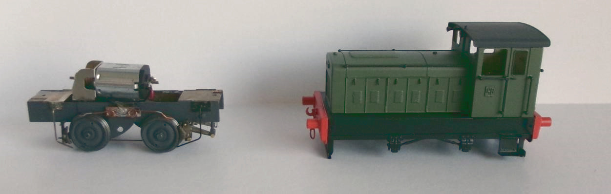
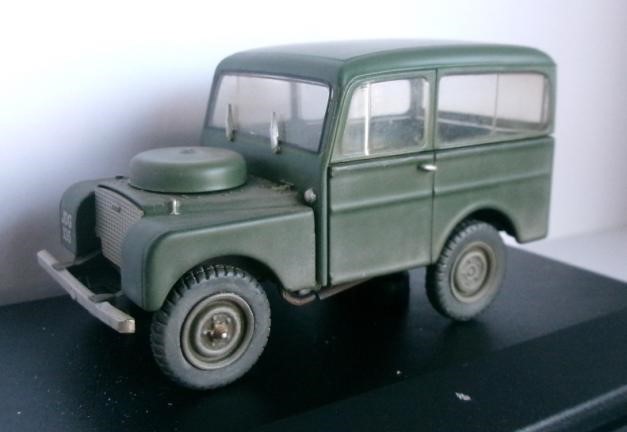
From Pete C, a 4mm Scale EM Gauge Ruston 88DS built from a Judith Edge kit, and perhaps more interestingly a weathered 7mm Scale Tickford bodied Land Rover intended for The Summit. These Tickford built Landies were marketed as a ‘Station Wagon’. They were better equipped than the standard Land Rovers and thus attracted Purchase Tax limiting sales. About 900 were produced, most were exported and few survive.