May, June & July 2026

May, June & July 2026

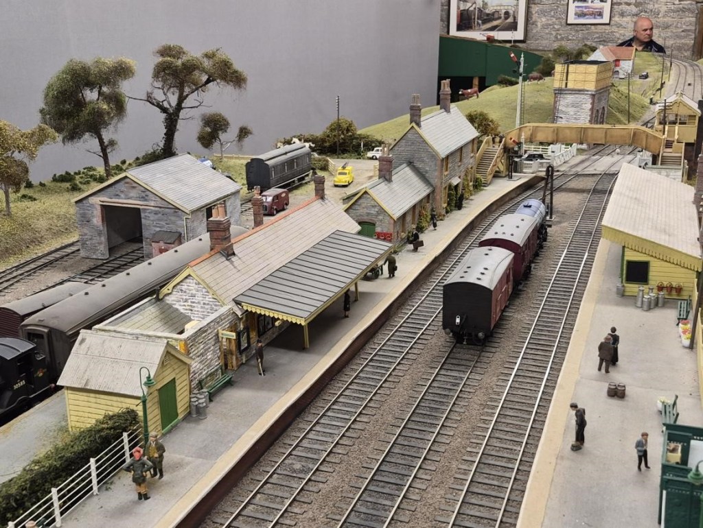
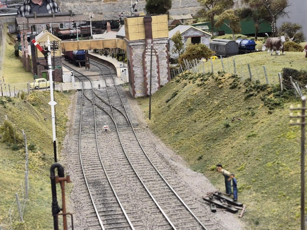
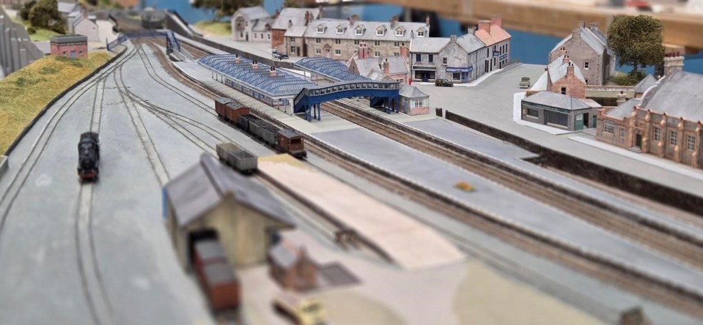
Allan is building a 7mm rendition of Cole on the much-lamented Somerset and Dorset main line, just south of its crossing over the GWR Berks & Hants line. The period that Allan is modelling is the late 1940s, hence the white lining to the platform edge. The building paint colours are LMS cream and brown. Purists will be critical of this. It was most likely the colours were SR green and cream (the restored Midsomer Norton station is in these colours) but in his choice to model the LMS he just couldn’t bring himself to see his black locos and maroon coaches trundle through a SR station!
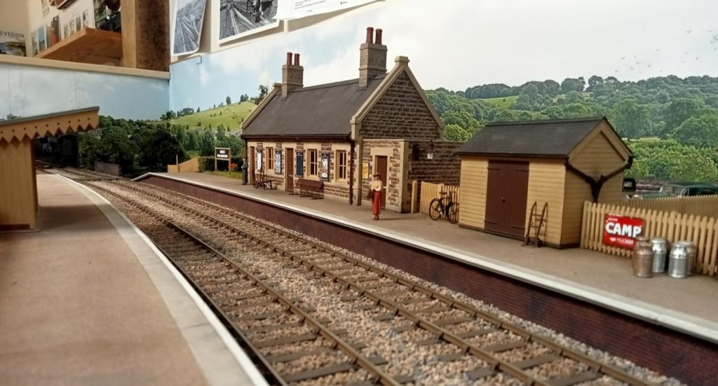
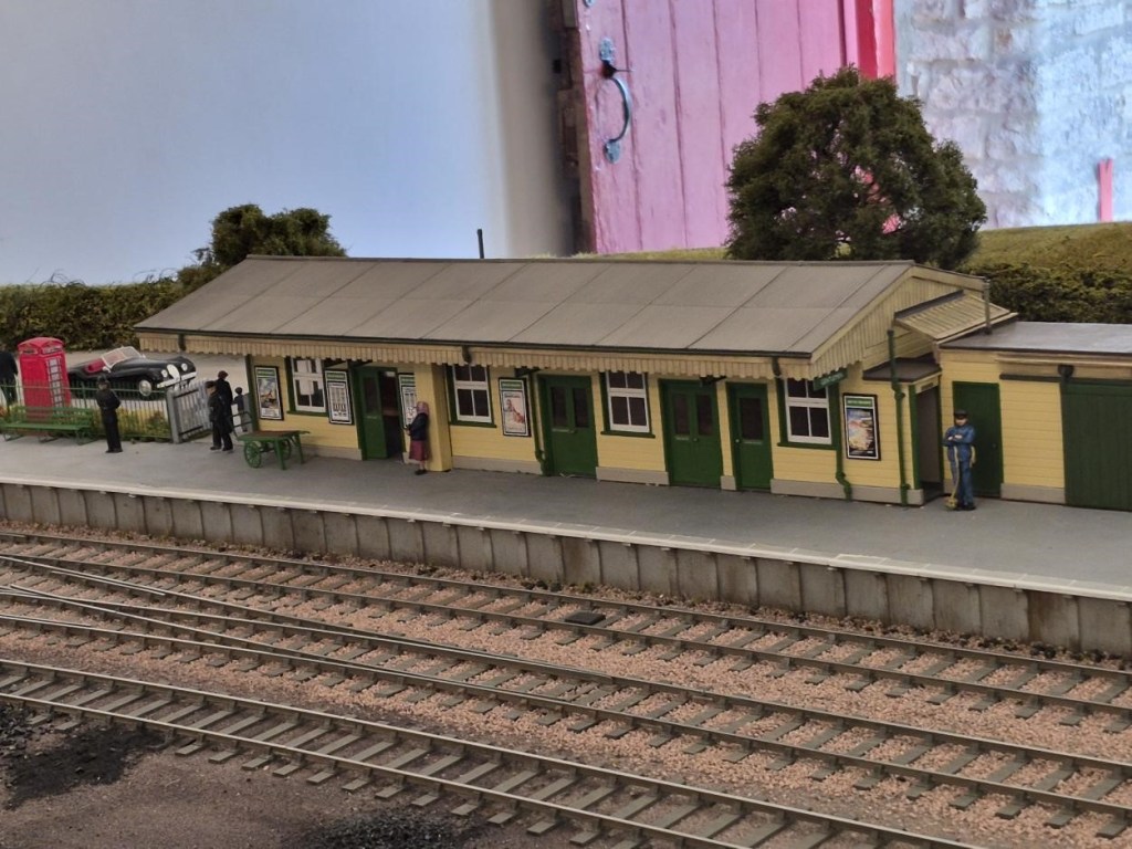
The station building is a replica of the real thing. Now a private house, Allan was able to measure and draw it thanks to the kind permission of the owner. The signal box, up platform shelter, shed and bridges are based on photographs and are near replicas of the real thing
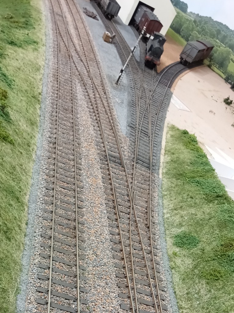
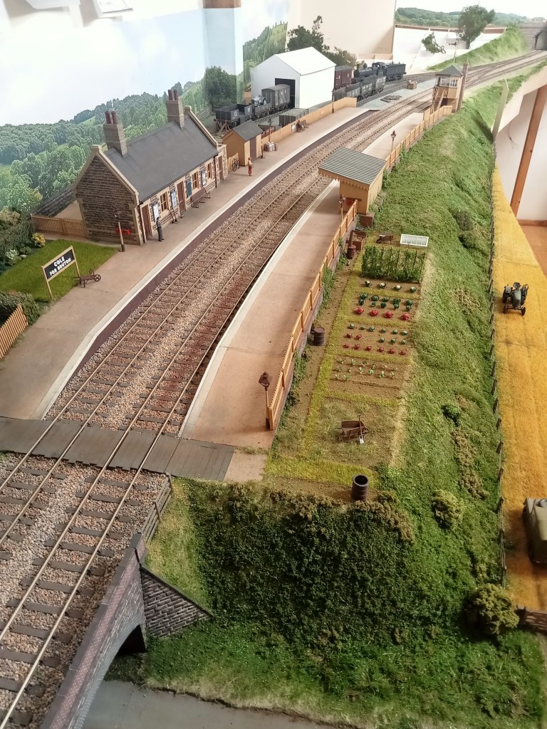
Allan has yet to build more than a placeholder for the goods shed which will be mostly imagined; he has one photo of it just peering above a passing train! It was demolished in the very late 1940s.
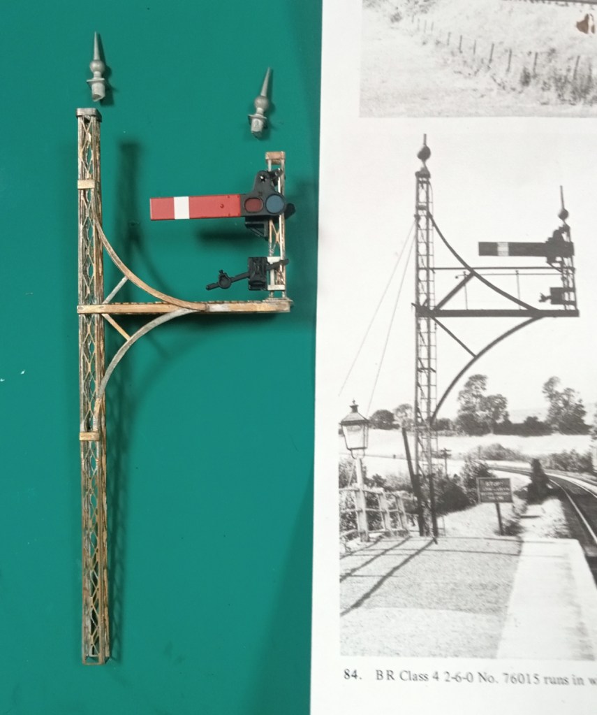
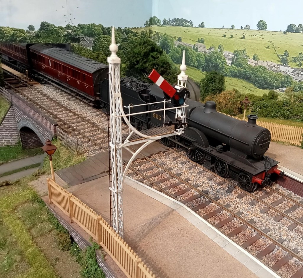
Allan’s recent project has been the creation of the very elaborate starting signal, shown clearly in this crop from a well known photo album. And the finished signal below.

Our new Chairman, Richard, has been fettling some truly superb Edwardian Great Western locos in 7mm scale. A particularly nice feature is working inside motion.
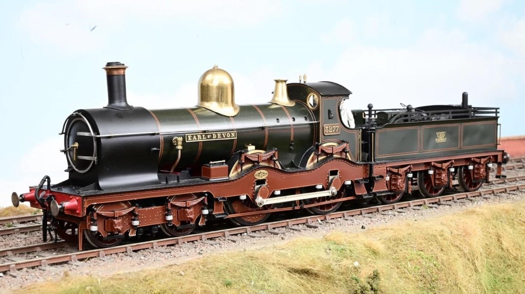
3277 was a Duke Class locomotive built in January 1897 for working the gradients of Devon and Cornwall, but these locos were spread around the GWR region in early 1923 when they were replaced by newer locos. In May 1930 the name was removed from the loco when it was rebuilt as an ‘Earl’ or ‘Dukedog’ class of locomotive. 3277 was withdrawn from service in April 1939. The model is from a Finney kit (builder unknown) and was painted by Alan Brackenborough.
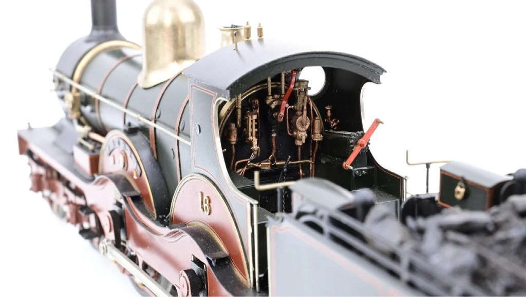
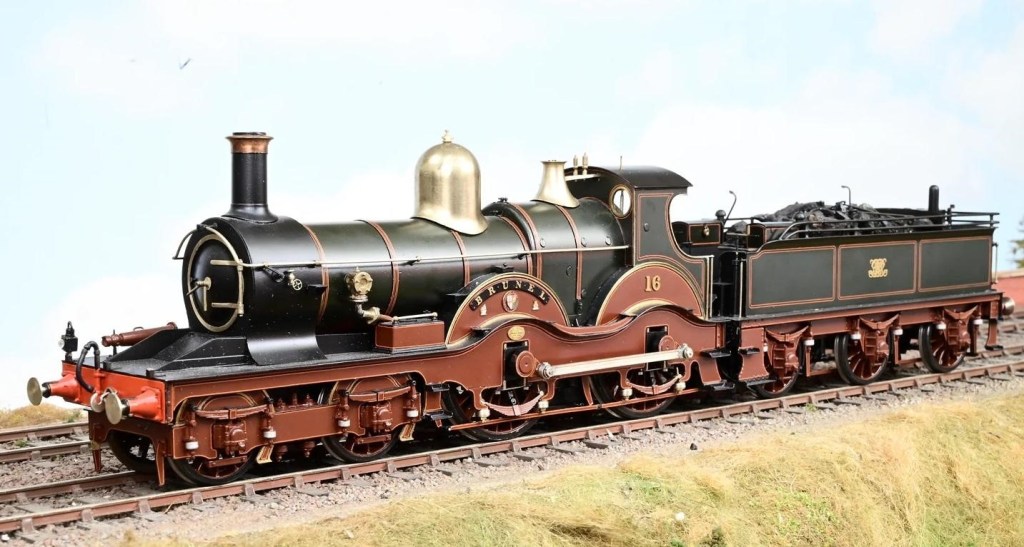
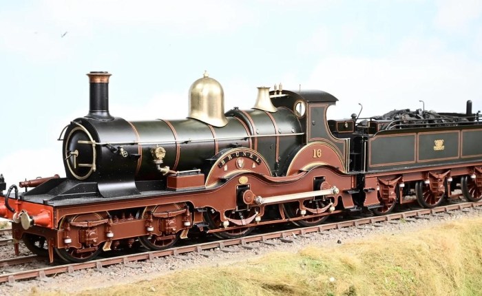
The Armstrong Class were a group of four locomotives designed by William Dean and built in 1894 with 7 ft 1.5 in (2.172 m) driving wheels. In April 1915 no. 16 Brunel was rebuilt with 6 ft 8.5 in (2.045 m) wheels and piston valves, having already been fitted with a Standard No.2 boiler. It was renumbered 4169 as a member of the Flower Class. The model is from an MOK kit, built by Bob Merry and also painted by Alan Brackenborough.
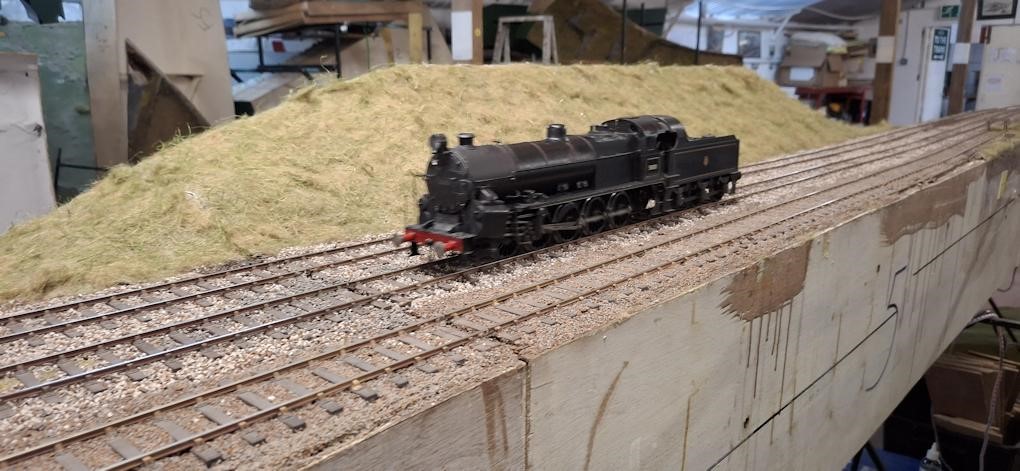
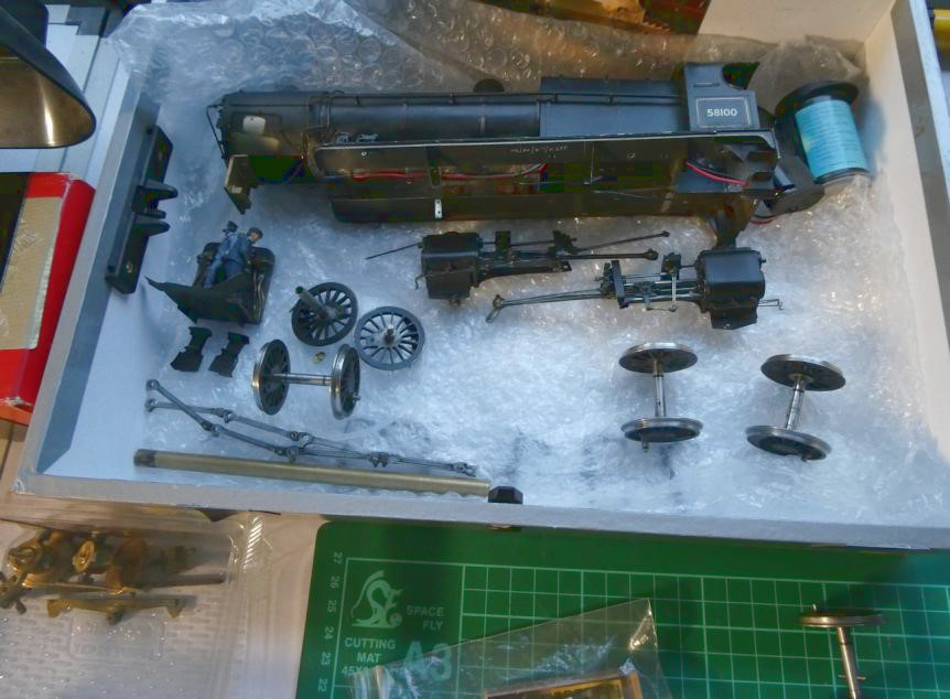
The completed Big Bertha (it needed brakes) running round “The Summit” in July. It ran faultlessly and is now home with its owner John, who is very happy with the result. Some details of Dave S fitting the brake gear: Big Bertha Repair in 7mm Scale, 0 Gauge – Part 3

With the Class 156 finished Steve made a start on the build of the Lion Class Stour, from his own design of etches and 3D printed parts. By June the superstructure and chassis were substantially complete and ready for wheels and chassis ready to be painted LSWR Umber.
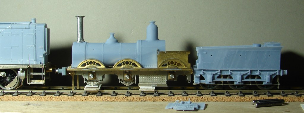
This is the revised boiler printed on his Mono 4K. It’s much more accurately formed with thicker walls (1.2mm), and was supported on a grid with knife edge supports to start the print properly. It has fixed cutouts for the splashers and variable cutouts for different gauge wheelsets, and as a result it is a much better fit to the etched parts. On the question of unfeasibly tall chimneys, the K’s chimney is a scale 5′ (same as the driving wheel diameter). A photo of the original Lion suggests that this relationship is entirely feasible, and as it happens it’s just a little taller than that on the AW Diseasel.
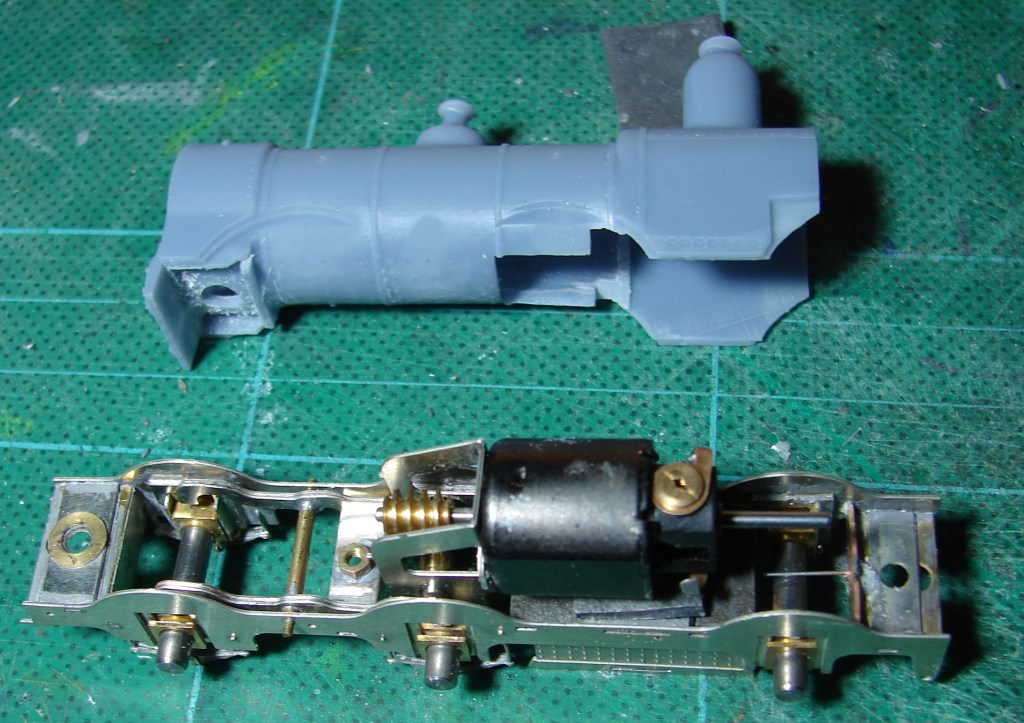
The chassis has the equalising beams and HLK RoadRunner gearbox built up and fitted. A steel wire has been soldered in as a sprung central pivot to give the crew a more comfortable ride. The grate area has been filled with sheet lead contributing a fair bit of weight. The rear motor shaft still needs to be removed. There will be some scope to add weight round the motor and above the wheels at the front of the rear splashers, as well as in the domes, smokebox and boiler. Seen are the fixed cutouts for the splashers and the additional cutouts needed for EM Gauge wheels which of course are inboard of where they should be. There’s plenty of room for the M1220, but only with the ends filed off the protruding motor fixing lugs. The centre bearing hornblocks and gearbox bearings had to be drastically thinned to get the 0.5mm side play required for a 3’6″ minimum radius curve.
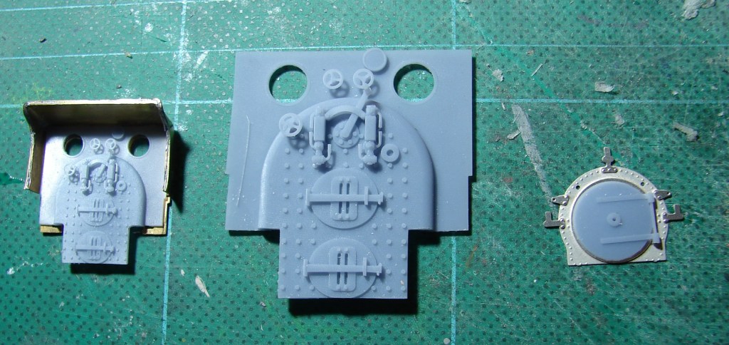
On mature reflection (in conjunction with someone who should know), the regulator has been moved to the middle and two gauge glasses fitted, one a mirror of the other. Whether they should have guards in 1884 is moot. On the left is a JH Beattie version of the revised backhead test fitted in the JH Beattie cab. In the middle the same in 7mm scale, printed with a view to encouraging a friend to build a 7mm scale Lion. On the right a nickel silver version of the smokebox front with handrail and lamp iron rivets set using a less pointed punch in his GW Models rivet press – with that it was much easier to centre the tool in the half-etched holes, thus ensuring that the embossed rivet is accurately placed.
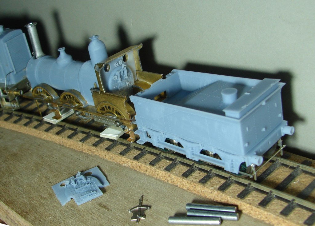
Steps assembled and fitted, and the rear splashers now soldered on. Quite fiddly, but no problems other than the slots being a fraction too wide. So far only 188C multicore solder has been used, carrying the solder to the job to burn off the unwanted resin flux in the process. The forward steps were a later upgrade to the Lions. Rather than cut the second shaft off what turns out to be his only M1220, He ordered an HLK 1219 coreless motor, and removed the M1220 so that the loco could be posed with the backhead in place. The motor is further forward in the Vesuvius and there might therefore be scope for a flywheel needing at least some of that second shaft. The reverser lever has been assembled (foreground). Height of top of the chimney from rail height is 54mm which is a scale 2″ greater than the LSWR loading gauge of 13′ 4″.
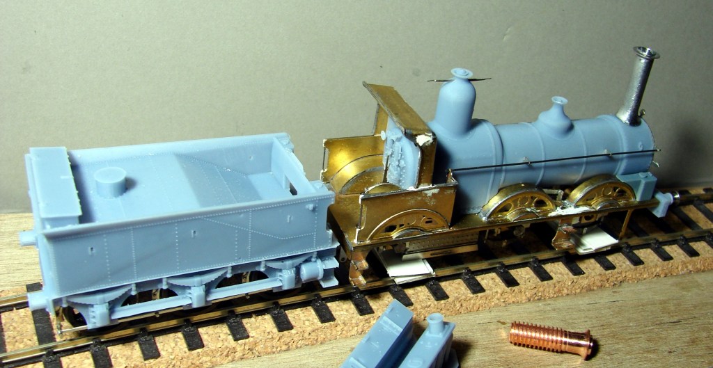
Handrail and etched handrail brackets fitted and 0.5mm steel wire loose fitted to confirm alignment (0.35mm wire looked too thin). In this photo something has been fretted out that looks like a reversing crank and rod between the leading wheels, in this case soldered to the outside of the narrow EM frames. The assembled reversing lever has also been soldered to the inside of the splasher in the cab. If this was 00 gauge there would be a temptation to solder it to the top of the splasher in correct alignment with the firebox sides. The cab has also been soldered in and some white Milliput used to fill some gaps, hollows and scrapes. The handrails have been fitted in the slot formed at the rear of the cab splasher and secured with the Milliput. Unfortunately it was very slow to go off and took a week to harden so suspect it’s actually ‘dried’.
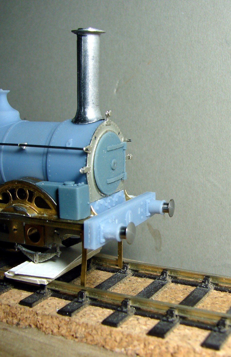
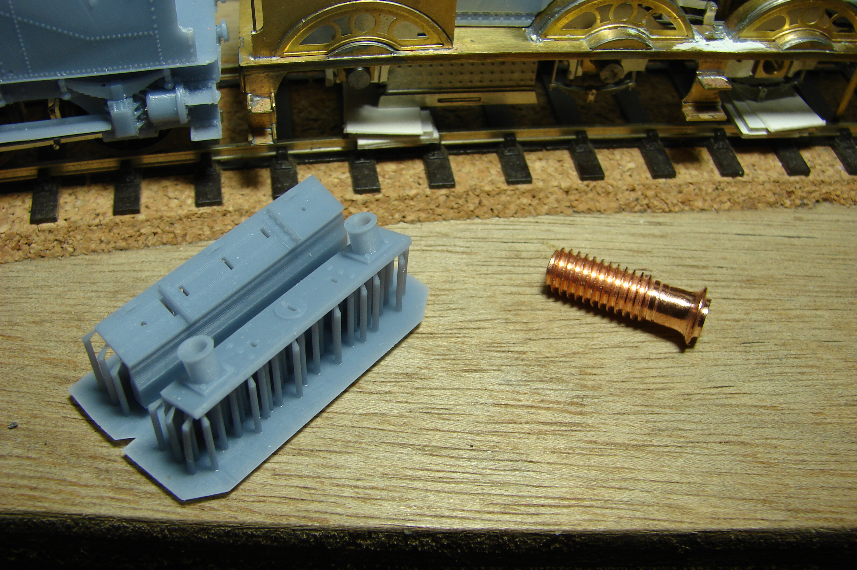
As usual it’s a photo (not the mk1 eyeball) that highlights that the smokebox door might not be fully home. 3D printing the buffer beam presented a problem in that it has two fair faces opposite each other, one of which must perforce be peppered with supports. Steve’s solution was to print it in two halves with a knife edge support at the bottom of each support and the fair faces printed at 20°. Both halves had to be thinned to compensate for ‘additive kerf’. A nice sliding fit was required for the AG buffers the shank of which was 3/32″ or 2.4mm. The housing was printed at 2.5mm diameter internally and that gave a perfect fit, but that took a couple of iterations to get exactly right. In the process Steve has been able to thin the walls of the housing to a nominal 0.34mm. As before the supports were added via Blueprint Studio and it was sliced in Anycubic Photon Workshop.

Also seen is his attempt at a copper capped chimney. Not being a GWR modeller Steve had no idea how nasty copper was to machine, but with files and cordless drill he eventually got somewhere close. The later Beattie chimney had a sloping top to the flange unlike the earlier ones, and Stour would have had that later chimney. Steve needs to cut chimney and cap square losing 1.5mm of height in the process, and that will be his next task, followed by painting wheels and frame LSWR Umber ready for assembly.
March & April 2026

March & April 2026

David’s Open Day in April featured both Nethercreech Junction and his new creation Lyme Regis. Some photos taken by YMRG members of Nethercreech Junction follow:

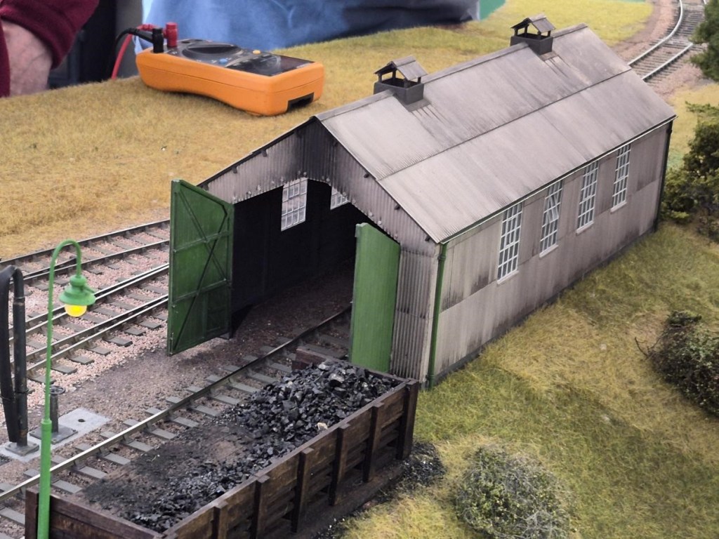
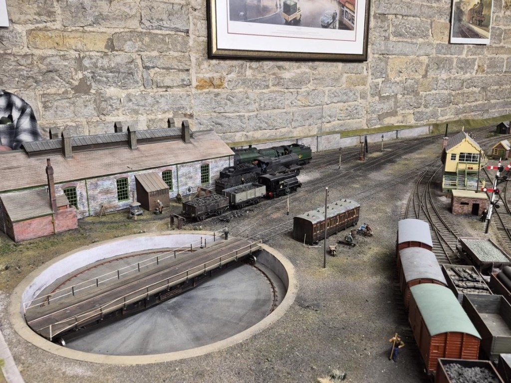
NetherCreech Junction Loco Depot
NetherCreech Junction Looking South
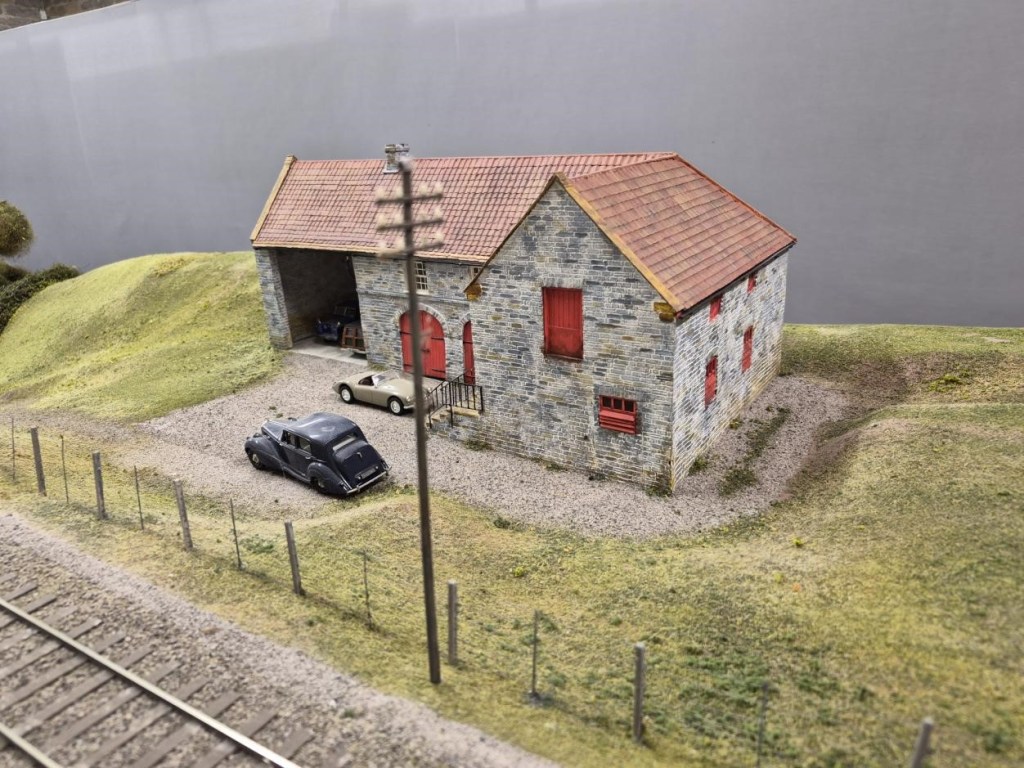
A Model of the Barn that Houses Nethercreech Junction and Lyme Regis painted in Estate Colours with Ivo Peters’ Bentley outside – as it really was on the Open Day!
Looking North towards the Level Crossing

And now two views of Lyme Regis. Member and retired architect Allan has been responsible for the buildings and excellent renditions they are too:

Finally, two further cameos at Lyme Regis:

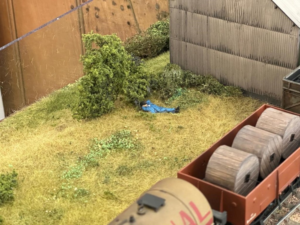
Looks like a nice place for a snooze.
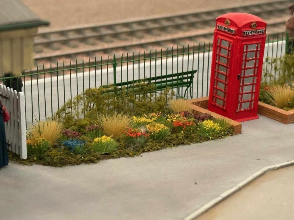
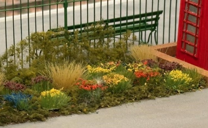
Is this the best flower bed on any layout in any scale anywhere?

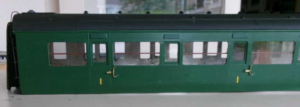
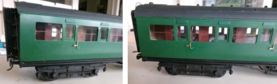
Pete C reports: The Maunsell coaches that the club bought from the estate of Simon K have had a few modifications and some repairs, one being a new bufferhead which had fallen off from a whitemetal buffer. A piece of brass was filed to shape and a spigot soldered in a hole in the buffer head to attach to the whitemetal housing. He then noticed that the cowling over the droplight windows had never been fitted, these were cut from plasticard and painted (luckily Railmatch paint was the same shade) then stuck on with thin superglue. The other noticeable missing items were the very prominent wooden handrails behind the corridor windows. Copper wire was painted and fitted to clips made from plasticard. The remaining job is to drill some holes in the solebar to secure the footboards properly.

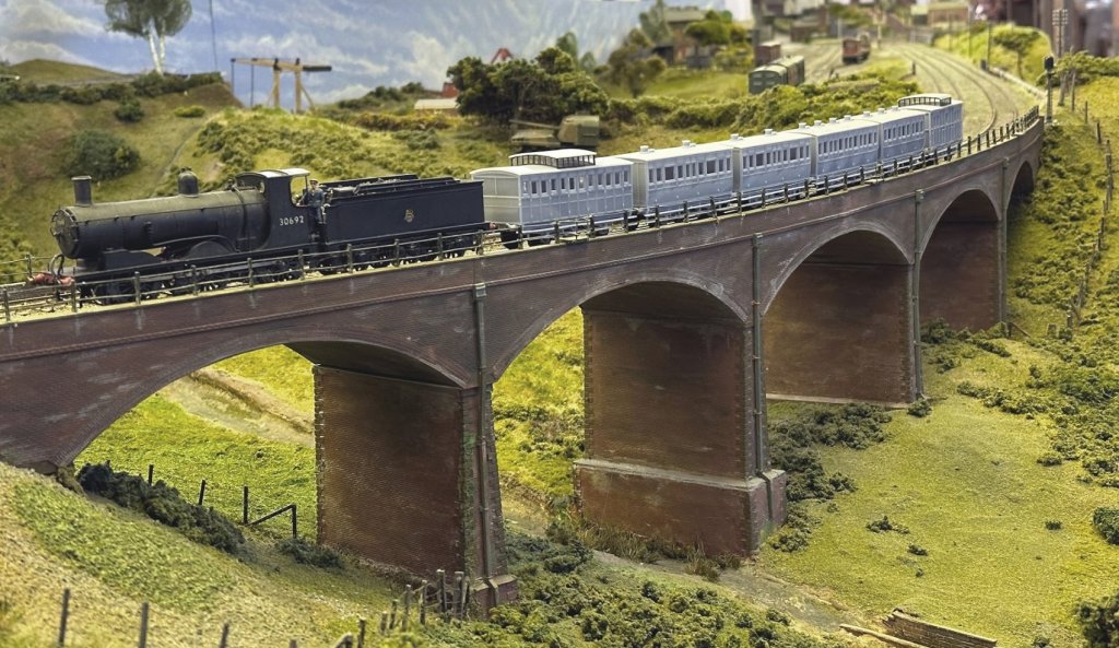
Steve has been steadily working through the many issues of 3D printing his LSWR coaches from the 1860s (in 4mm scale EM Gauge). Courtesy of Keith, not the Downton Train Crash formation of 1884, but a very close coupled rake of 3D printed coaches of all the required types crossing Bob Alderman’s viaduct on South Junction. The 1864 Passenger Brake is leading two 1865 Thirds, an 1862 Second and 1862 First, with the 1859 Passenger Brake bringing up the rear.

The Black Motor 30692 is the least inappropriate engine that he currently has to haul them, although it is at least a Sal&D engine. Built from a Jidenco kit by someone who had some idea of what they were doing and bought secondhand. The somewhat undercooked Jidenco 00 Gauge underpinnings were replaced using Persy chassis kits built to EM Gauge. Those familiar with Steve’s projects will guess that this could be made more complicated than it really needed to be: https://yeovilmrg.org/black-motor-re-chassis-in-em-gauge/

Finally Part 2 of the Big Bertha saga that could be a trilogy if it includes fitting the brake gear.

January & February 2026

January & February 2026

Jim has concluded that CS2 is not the best place to try and make something of the ‘Aberdeen White Elephant’, otherwise known as the ginormous 2mm finescale fiddle yard that I carted down from its namesake in north east Scotland (ie Aberdeen!) in the summer of 2019 and done little with since, due to (a) Covid and (b) his house move to Exeter in 2022.

Despite the loft in his bungalow having insufficient headroom to stand up in, and the loft hatch being unable to accommodate 8ft long baseboards, he has decided that he can make a better fist of it there than he first thought, and it will remove the need for regular 100 mile return trips back to Somerset.

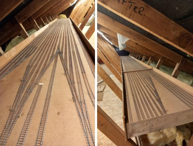
Accordingly, he ‘bit the bullet’ a few weeks ago and carefully cut a few millimetres out of all the rails (36 at every baseboard joint with 18 parallel storage roads) followed by gently sawing through the MDF baseboard top to convert three baseboards 8ft long into six baseboards 4ft long. All six boards are now up the loft at home and, simultaneously, I am adding raised flooring to gain access right down the length of one leg of the roof space. Below is a picture showing four of the boards, with two more to be added at the far end, before a corner is added:

The second picture is taken from the other end and shows the fifth “half-board” added and more of the new flooring to the left. Of note is the relatively little vertical leeway Jim has to insert cross struts to support the boards more positively.

In May, the 2mm Scale Association is having its usual show at the Derby Conference Centre and this year it is all weekend, rather than just Saturday, and the star of the show will be Dunallander, which this fiddle yard was originally built for. Included in the van from Aberdeen this time will be the Perspex sheets that cover the fiddle yard boards which Jim forgot to collect in 2019!

A reminder that the scenic side of the layout has yet to be started but, in comparison, will be very simple and comprise a double track main line, with overhead 25kv catenary (!) and mineral exchange sidings and a branch leading to Littleton Colliery, near Cannock in Staffordshire. In contrast, the Grampian Area Group of the 2mm Scale Association, who was persuaded to save the scenic side of the original layout, have strived to construct an almost exact copy of Dunblane Station and its immediate environs, involving many, many buildings – see photo above at the Elgin Show. In contrast Jim’s rendition of Bungham Lane, Penkridge only needs one building, the junction signal box!

February saw Part 1 of the Big Bertha Repair ending on a cliff hanger see the link below:

Next up Steve’s Lima Class 156 Upgrade incorporating his own and Hurst Models resin 3D printed parts:

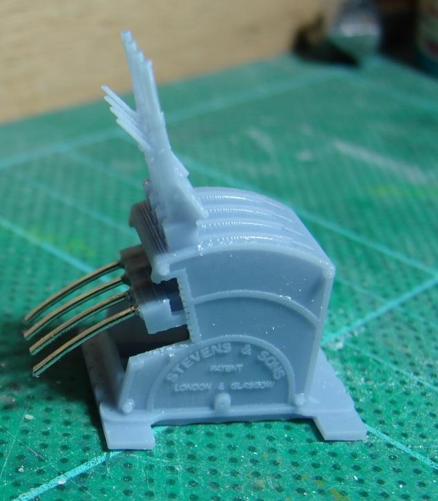
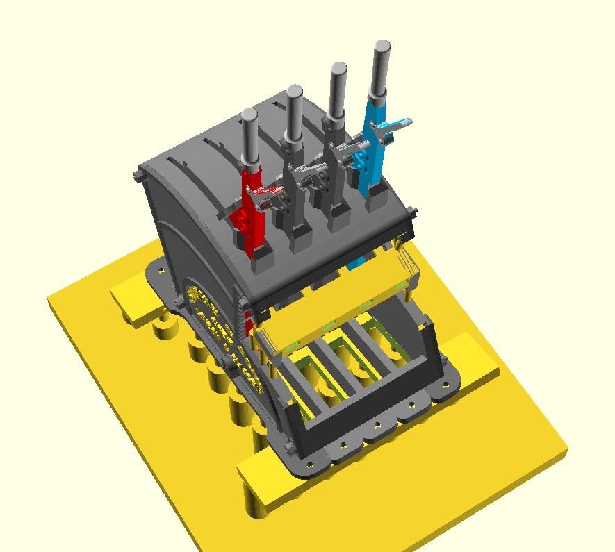
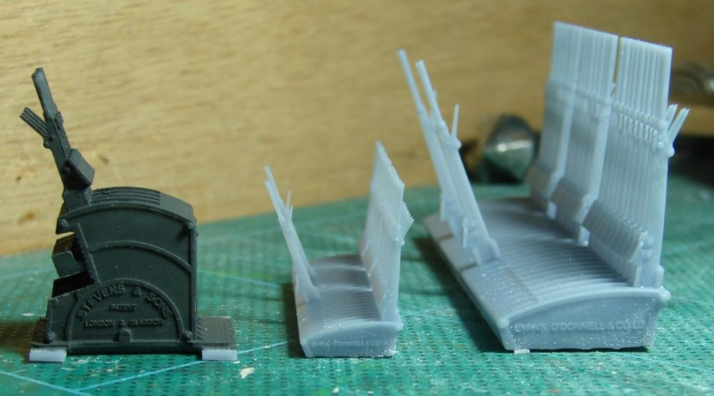
Steve is modelling Verwood in EM Gauge, and needed a Stevens style lever frame for the box plus a Stevens style Knee frame for the ground frame that was at the West Moors end of the loop. He’s 3D modelled these in QCAD and OpenSCAD and is 3D printing them in 4mm and 7mm scale on his AnyCubic Photon Mono 4K in AnyCubic ABS-Like Water Washable Resin 3.0. Both can be configured to have LSWR or SR style plates and with any number of levers. Could the models be 3D printed though?

This is a 7mm scale version of Steve’s 3D printed LSWR style ground frame for Verwood with some overly thick tails fitted to the locking frame. The clearness of the text suggests to Steve that his BR(S) smokebox plates (with curly 6s and 9s) could probably be printed vertically rather than on the bed allowing me to batch them up on a raft and remove and prepare them as required.

A test print showed that when tilted up on supports for 3D printing, the void under the tails needed to be more realisticly modelled (almost empty bar framing) so that it could drain of resin and water during washing. Win-win!

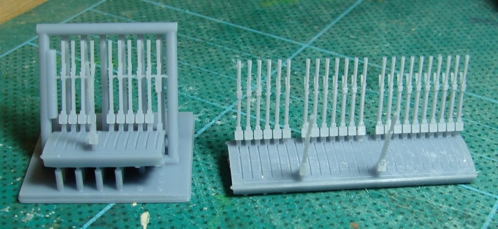
On the left a reject ground frame with coat of Humbrol Dark Grey to bring it to life. Also ‘Privett’ LSWR era frames in 4mm and 7mm scale with just the FPL levers reversed, as these frames were for most of the day waiting for something to happen. These sort of frames were not untypical of the Meon Valley and other somewhat overbuilt lines of the same period.

On the left a lever frame for Verwood in the final version of the support cradle. As with the ‘Privett’ frame on the right, what should have been the only FPL is pulled awaiting the next train – that was a mistake as it should have been Lever 4! The Privett frame was fairly easy to release from the final version of the support cradle with nicely aligned levers. It looks like some of the supports for the Verwood frame went AWOL but recovered just in time! There were a lot of iterations of the support cradle before it worked reliably every time.

April 2024

This month some ‘proper’ modelling, followed by ‘virtual’ modelling.

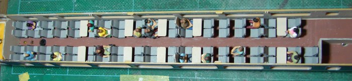
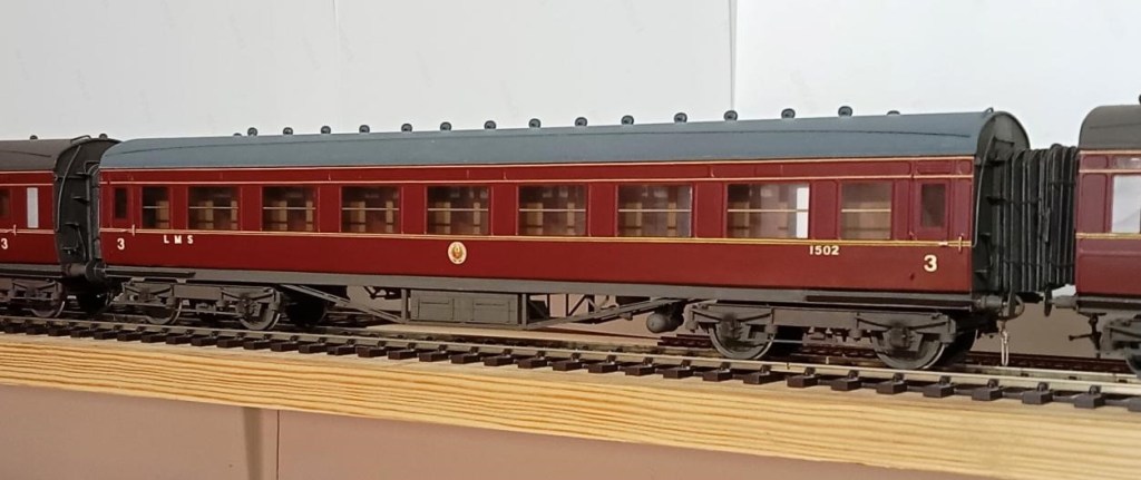
Allan has finished another of his 7mm scale LMS coaches, this lovely example, from the single window with square corners would be a period II corridor third – from another Sidelines kit.

Obviously relishing the challenge of turn-of-the-last-century intricate livery paintwork, Dave Haines has produced the next 7mm scale coach for his “Wellsy” layout. This one is a 58 ft long luggage tricomposite, originally built in 1899 for the Birkenhead to Folkestone/Deal through trains run with the SER. They turned out to be very useful as through carriages all over the system so they built twenty of them in the end. They had six lavatories so it’s surprising there was any room left for passengers let alone their luggage! It’s all plastic except for the Slaters bogies (the long wheelbase version that Dean used for his later coaches) and a few fittings, scratch built using David Jenkinson methods and painted using Ian Rathbone methods.

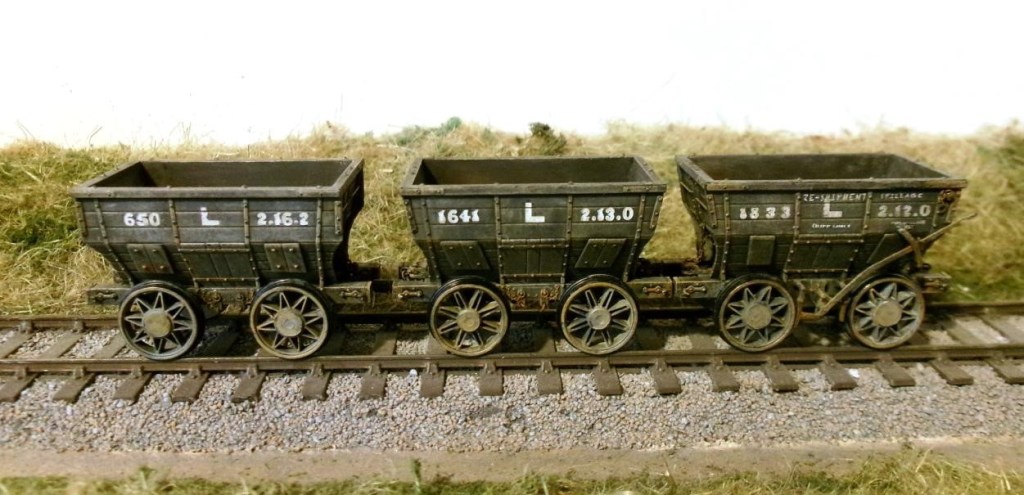
A few evenings work by Peter has dramatically improved the 4mm scale EM Gauge Accurascale Chaldrons that he bought a while ago. Subtle weathering has bought the detail out from the original plain black satin finish.

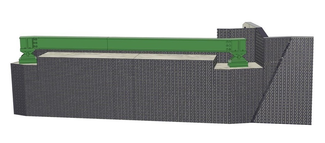
Over the last month Andrew has been working on the flyover bridge for Heyno Junction, the club’s OO gauge layout. It is based on the Aynho Flyover on the Chiltern line. The model has been produced in Fusion360 CAD software and he has started to print out the brick base on his 3D printer. It has been really tricky to do the brickwork as the process makes the computer struggle with long waits while the computer worked out the pattern (he could do with a more powerful computer). The first section took over 20hrs to print out and the 2nd section took over 17hrs. He has started to build up the metal work of the bridge into sections so they can be printed out and assembled

Whilst at CS2 Steve gave his 3D printed AW diseasel disaster a run out on South Junction, which it plodded around for about an hour without managing to fall off. This was after its trip to Martin Finney’s
Semley where this model to EM Gauge serenely clambered over and through two sets of P4 points in both directions without derailing. During this feat it was noticed that after 18 years the original tyreless AG gearwheel had cracked and slipped on the jackshaft axle leading to a slight ‘hop’ on each revolution. This gear wheel has now been replaced by its previously redundant twin (on a slightly shortened axle) with the steel rim retained, the spokes covered over, balance weight fitted and the flange filed off. Steve hadn’t appreciated that he needed macro mode on his new to him Sony camera (2011) for it to focus properly for a shot like this that he wouldn’t have previously considered any sort of close up.

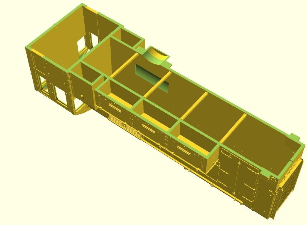
The glazing pockets on the trial 3D print were not satisfactory as I hadn’t made enough allowance for 3D printed items being a little larger than specified – by about 0.1mm and mainly a problem with holes. Thin bubble packaging film could be slid into the side window and door glazing pockets, but not into the front and rear window pockets. To get round this the pockets are now 0.45mm (for .010″ Plastiglaze), and holes have been added above the affected windows to aid resin drainage during printing.

To aid the printing process a sliver of extra material has been added at the bottom of the body for trimming. The fuel and battery boxes have been boxed in, and braces placed across the base of the bonnet to keep everything aligned during printing and cleaning. This render pre-dates that test run on SJ with the larger gear wheel that has required additional clearance to be added under the gear wheel cover.

Lastly a helpful Western Thunder user posted a very useful and clear photo of the prototype from a new angle from which detail could be added to the gear cover area (speedo drive cable and oilers). I also used it as a reference to develop some artwork for the WD transfers.