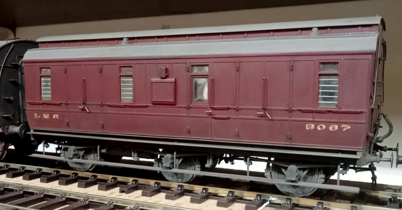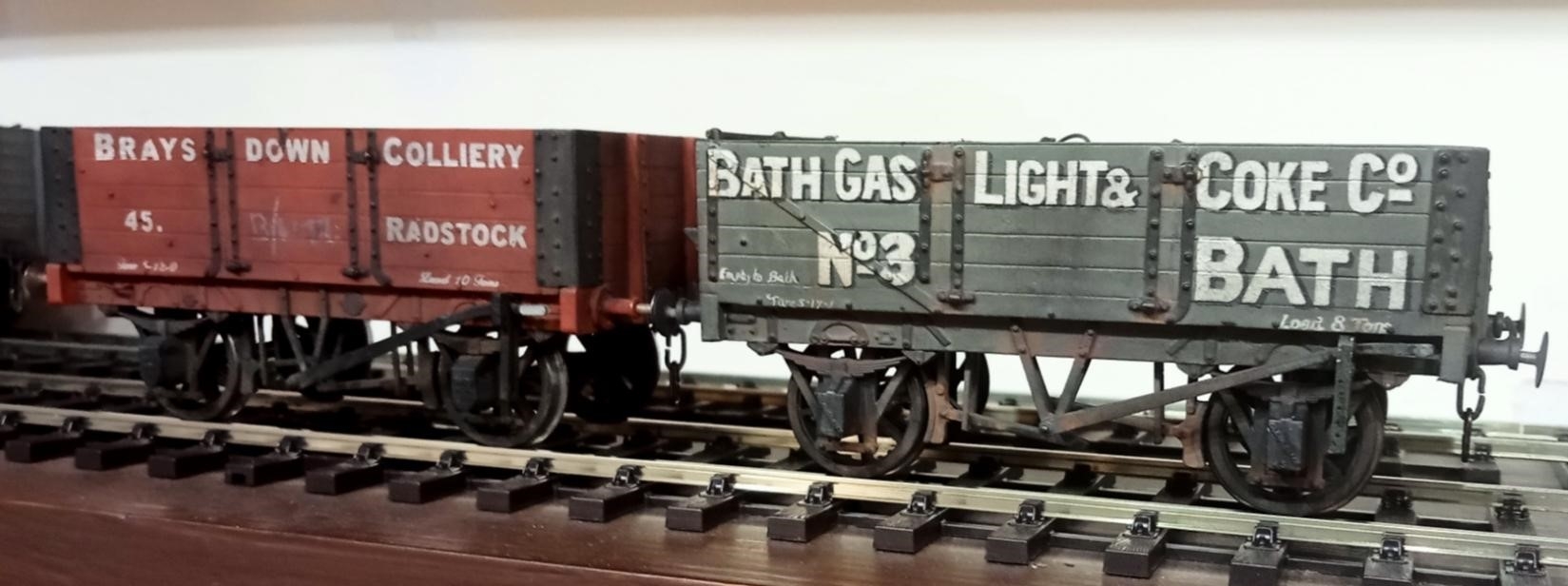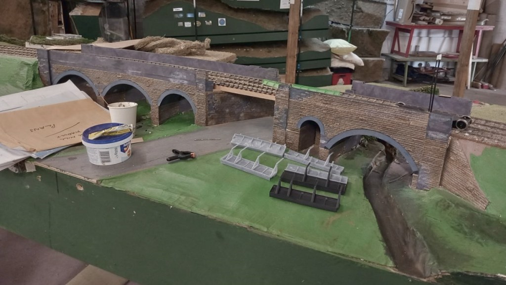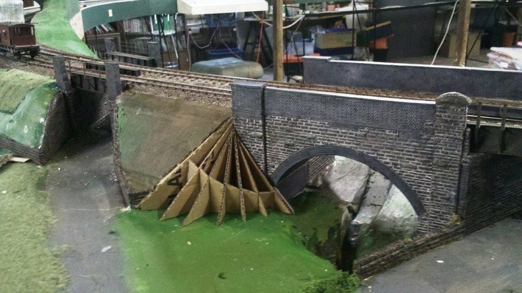
May, June & July 2026

May, June & July 2026

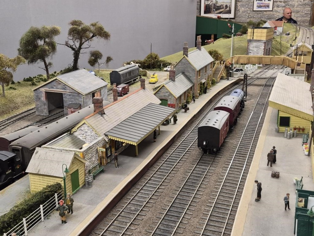
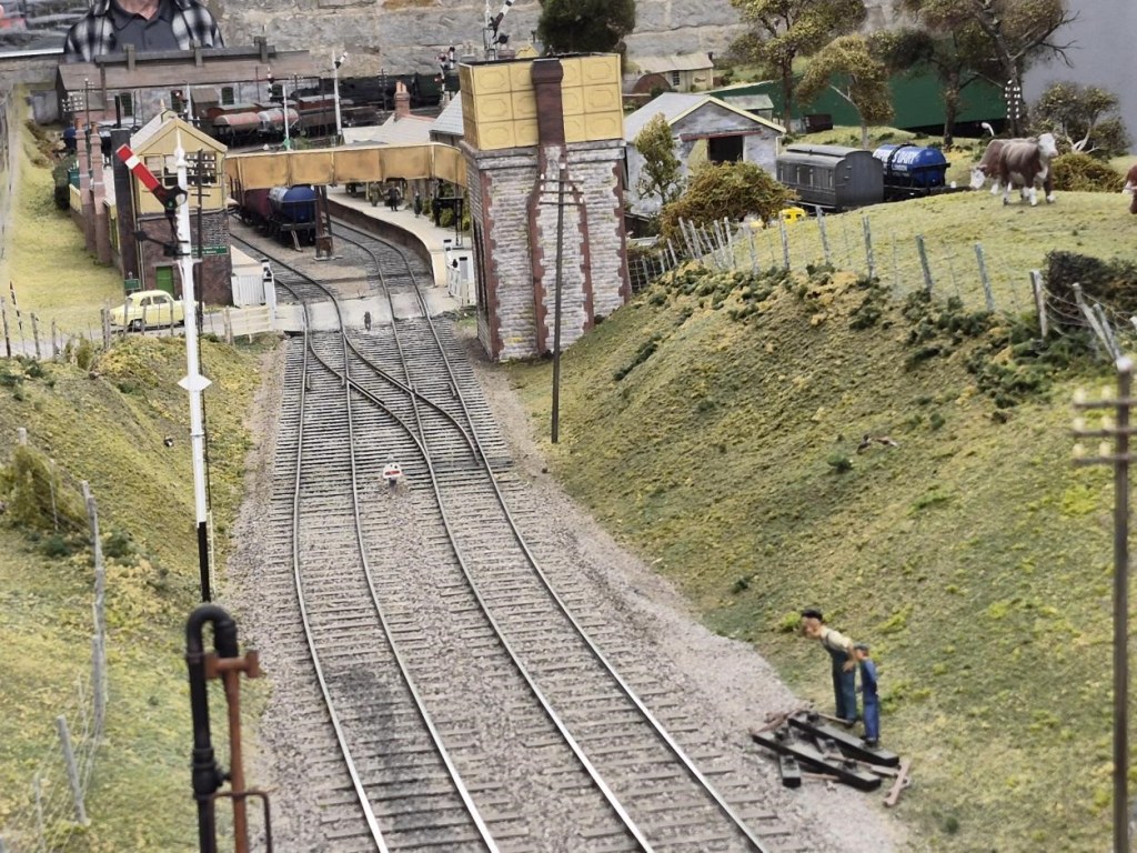
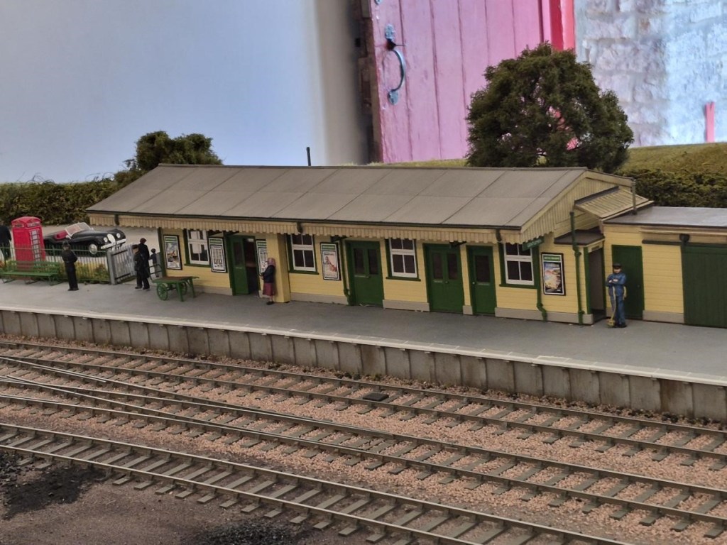
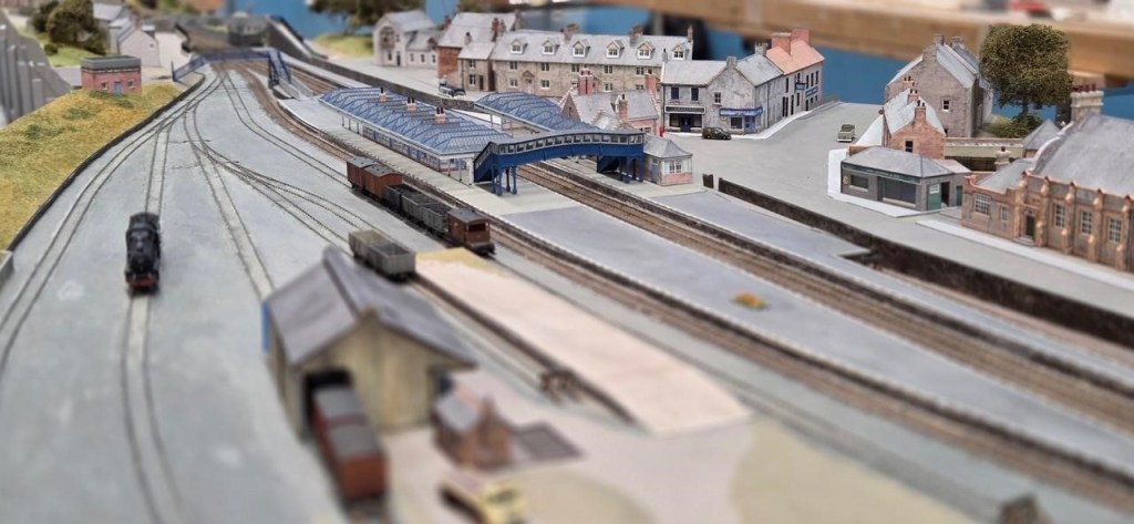
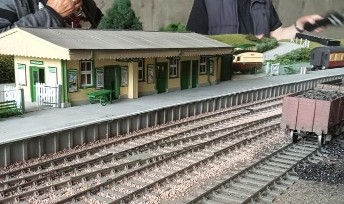
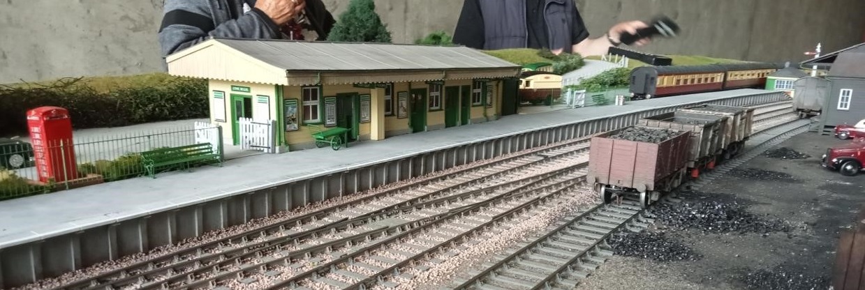
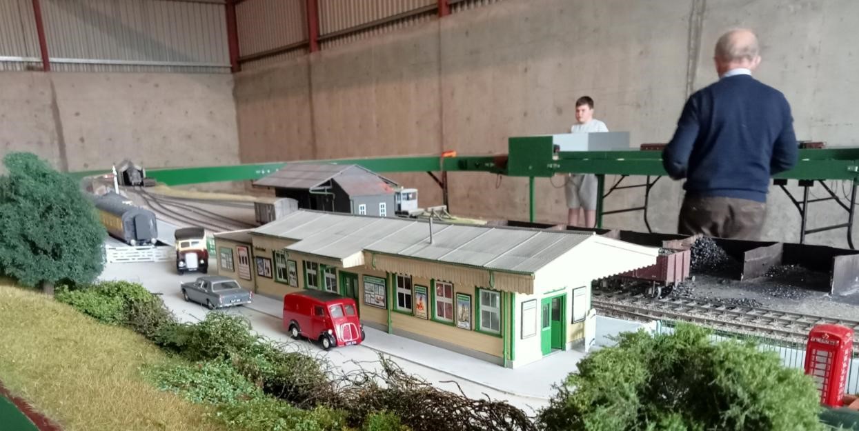
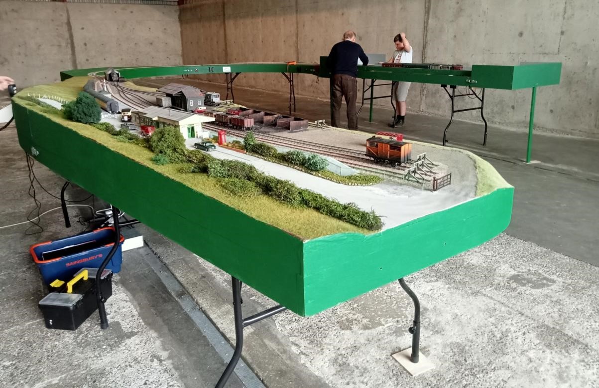
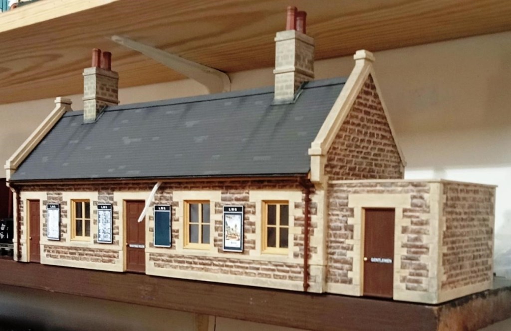
Allan is building a 7mm rendition of Cole on the much-lamented Somerset and Dorset main line, just south of its crossing over the GWR Berks & Hants line. The period that Allan is modelling is the late 1940s, hence the white lining to the platform edge. The building paint colours are LMS cream and brown. Purists will be critical of this. It was most likely the colours were SR green and cream (the restored Midsomer Norton station is in these colours) but in his choice to model the LMS he just couldn’t bring himself to see his black locos and maroon coaches trundle through a SR station!
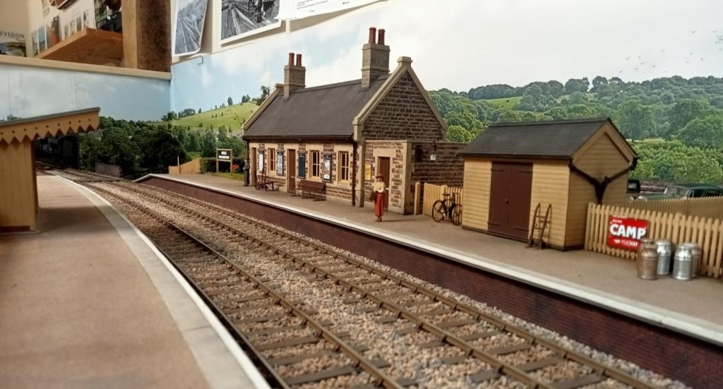
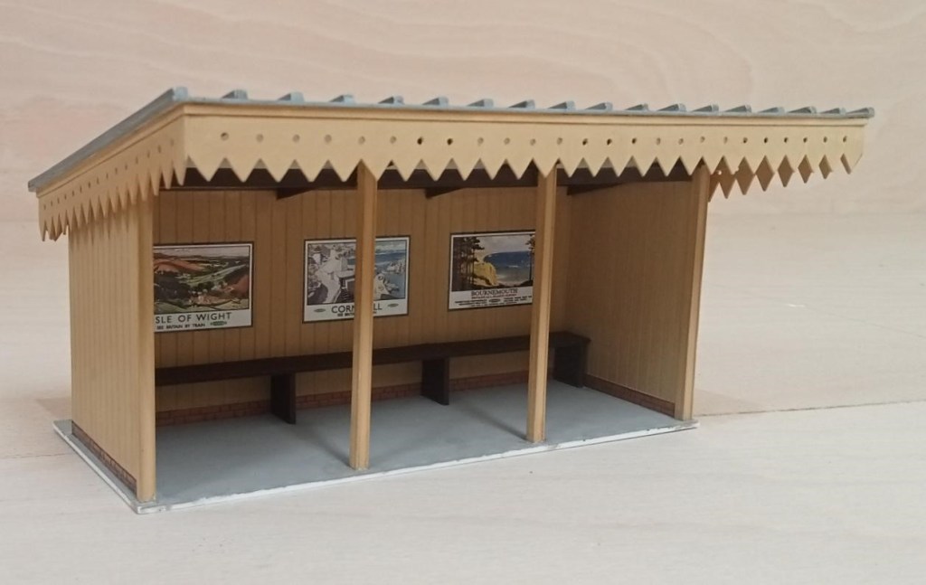
The station building is a replica of the real thing. Now a private house, Allan was able to measure and draw it thanks to the kind permission of the owner. The signal box, up platform shelter, shed and bridges are based on photographs and are near replicas of the real thing
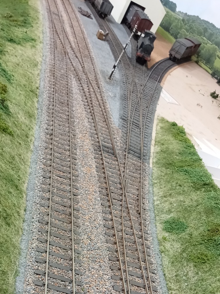
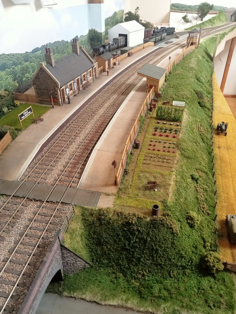
Allan has yet to build more than a placeholder for the goods shed which will be mostly imagined; he has one photo of it just peering above a passing train! It was demolished in the very late 1940s.
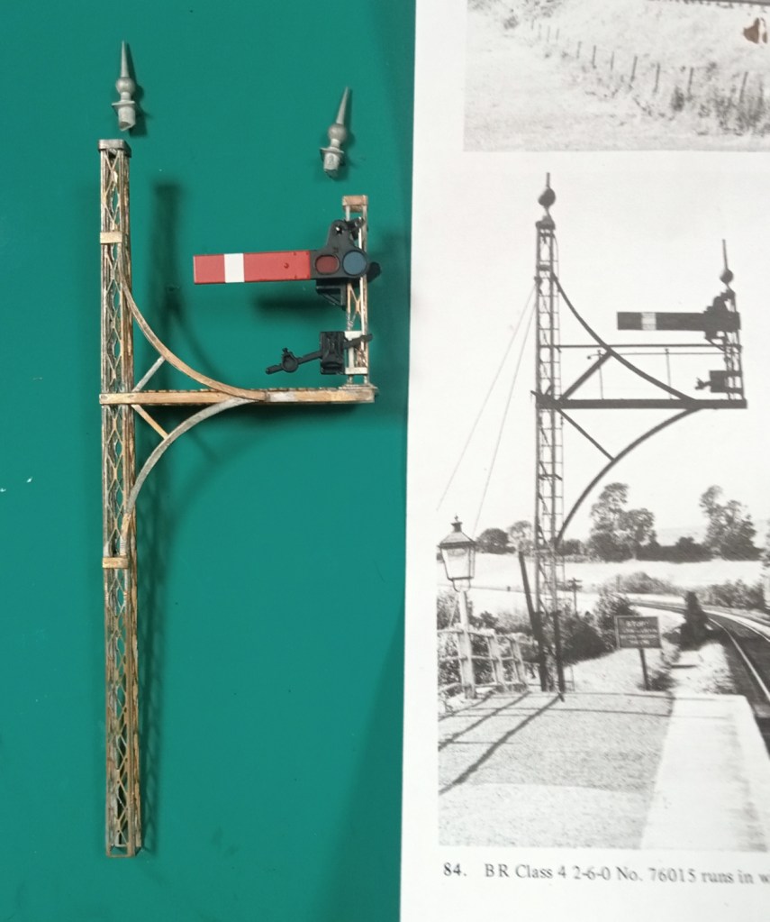
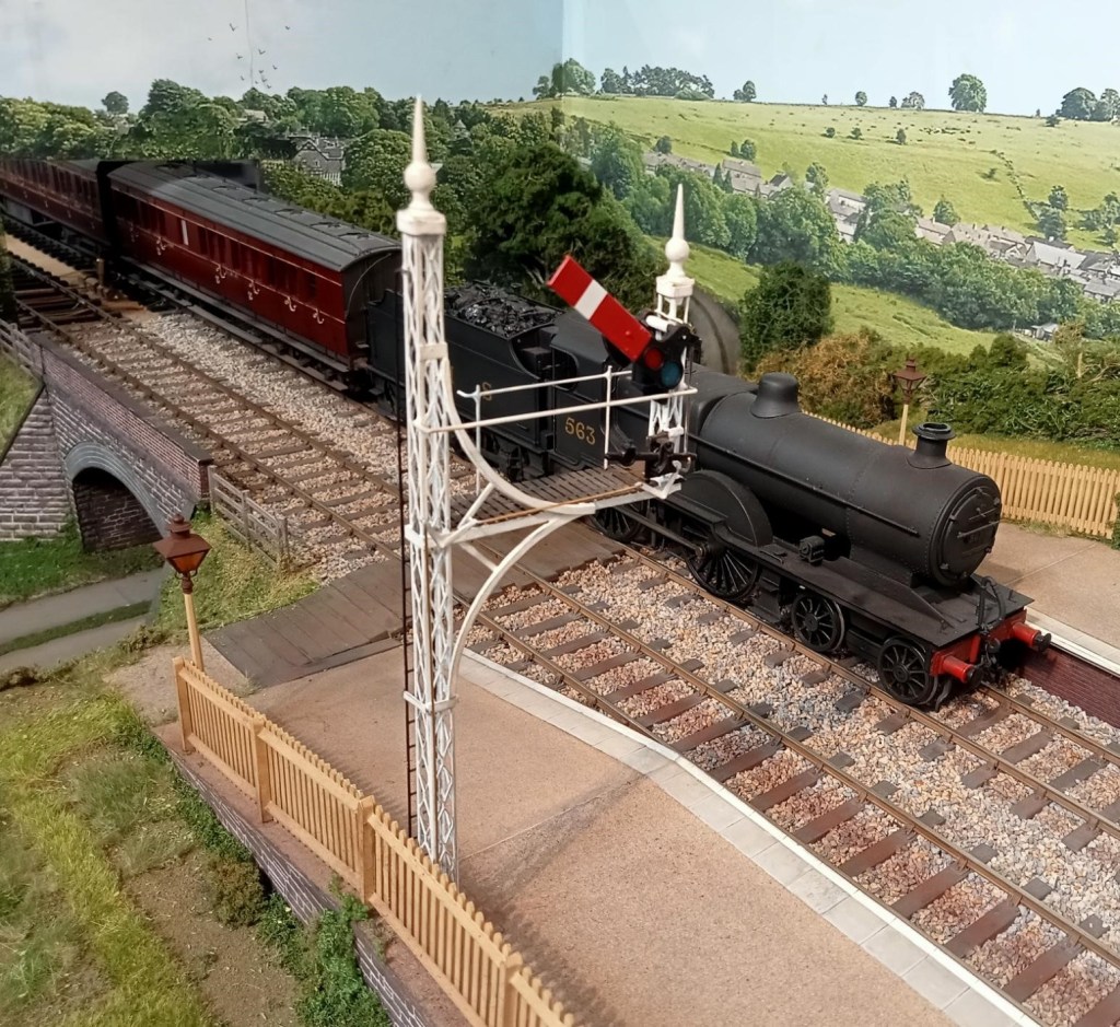
Allan’s recent project has been the creation of the very elaborate starting signal, shown clearly in this crop from a well known photo album. And the finished signal below.

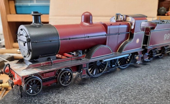
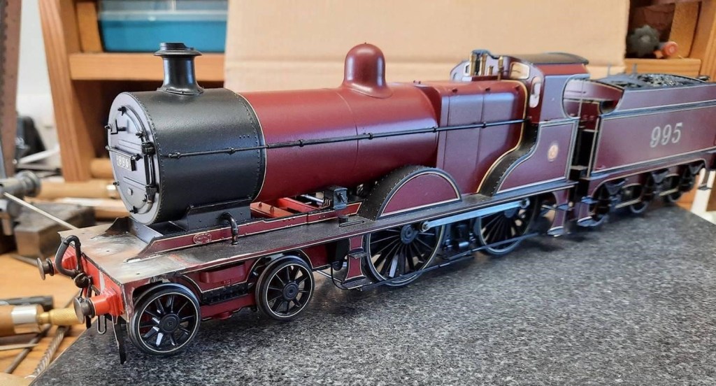
Our new Chairman, Richard, has been fettling some truly superb Edwardian Great Western locos in 7mm scale. A particularly nice feature is working inside motion.
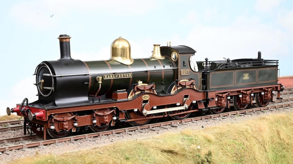
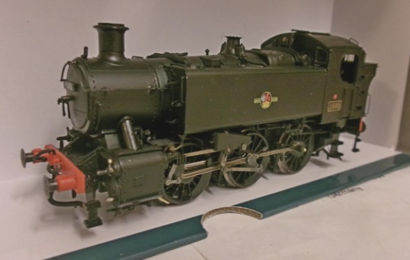
3277 was a Duke Class locomotive built in January 1897 for working the gradients of Devon and Cornwall, but these locos were spread around the GWR region in early 1923 when they were replaced by newer locos. In May 1930 the name was removed from the loco when it was rebuilt as an ‘Earl’ or ‘Dukedog’ class of locomotive. 3277 was withdrawn from service in April 1939. The model is from a Finney kit (builder unknown) and was painted by Alan Brackenborough.
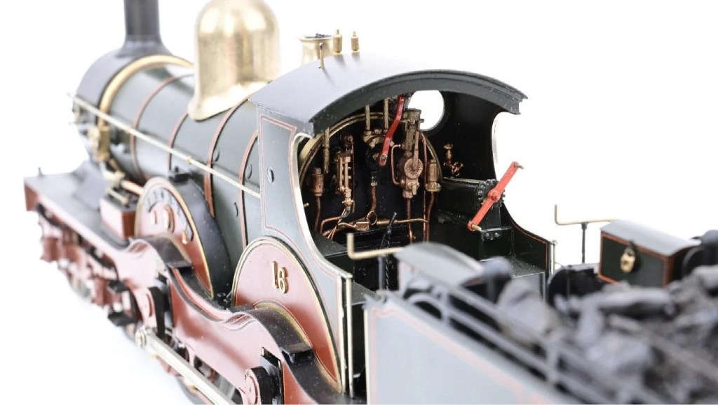
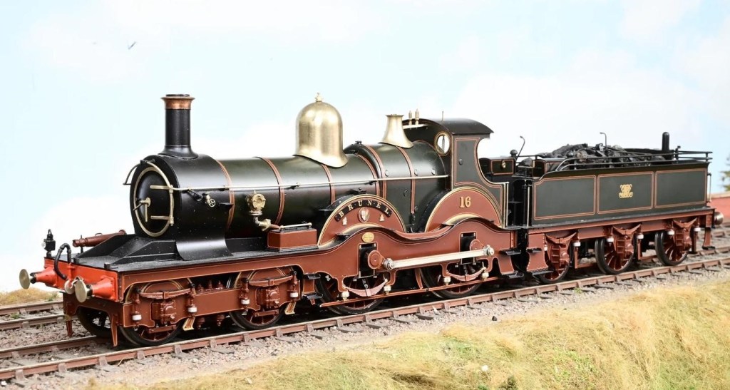
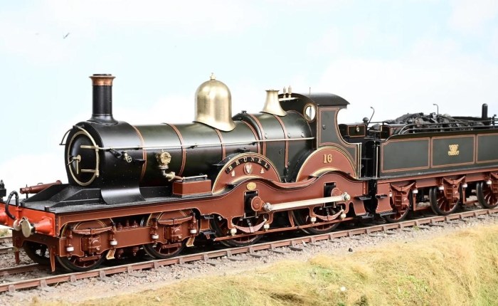
The Armstrong Class were a group of four locomotives designed by William Dean and built in 1894 with 7 ft 1.5 in (2.172 m) driving wheels. In April 1915 no. 16 Brunel was rebuilt with 6 ft 8.5 in (2.045 m) wheels and piston valves, having already been fitted with a Standard No.2 boiler. It was renumbered 4169 as a member of the Flower Class. The model is from an MOK kit, built by Bob Merry and also painted by Alan Brackenborough.
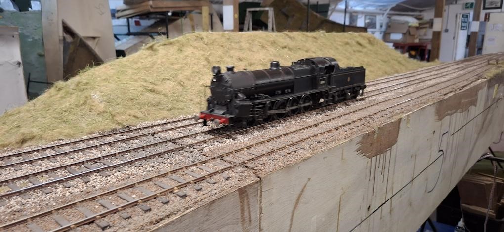
The completed Big Bertha (it needed brakes) running round “The Summit” in July. It ran faultlessly and is now home with its owner John, who is very happy with the result. Some details of Dave S fitting the brake gear: Big Bertha Repair in 7mm Scale, 0 Gauge – Part 3

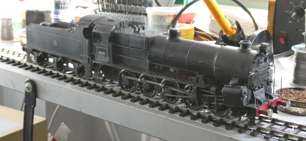
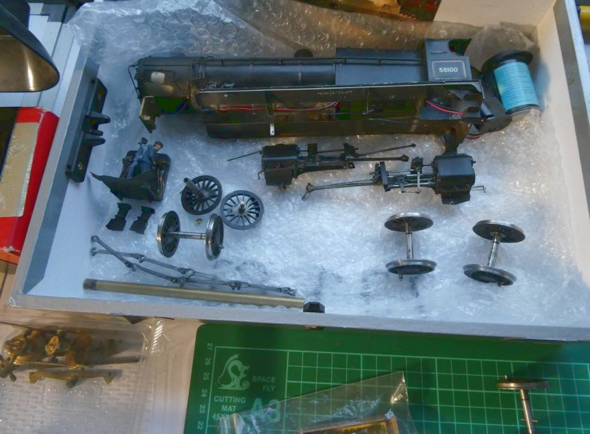
With the Class 156 finished Steve made a start on the build of the Lion Class Stour, from his own design of etches and 3D printed parts. By June the superstructure and chassis were substantially complete and ready for wheels and chassis ready to be painted LSWR Umber.
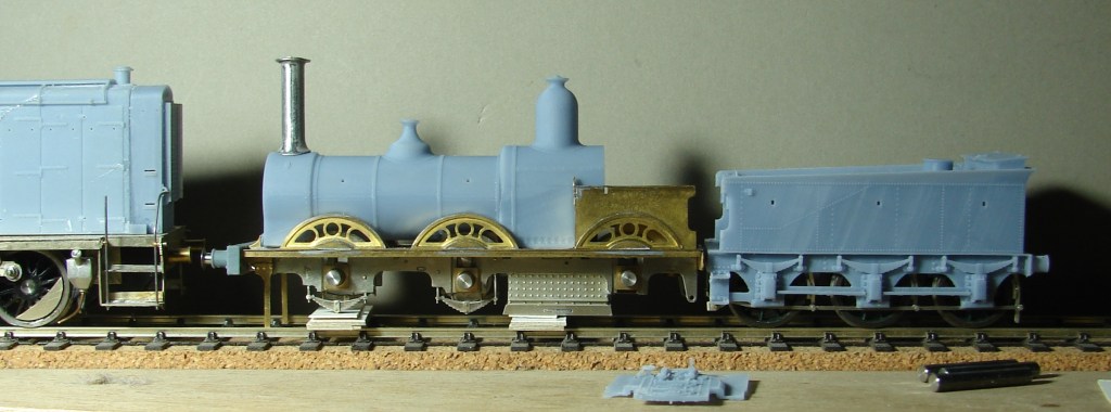
This is the revised boiler printed on his Mono 4K. It’s much more accurately formed with thicker walls (1.2mm), and was supported on a grid with knife edge supports to start the print properly. It has fixed cutouts for the splashers and variable cutouts for different gauge wheelsets, and as a result it is a much better fit to the etched parts. On the question of unfeasibly tall chimneys, the K’s chimney is a scale 5′ (same as the driving wheel diameter). A photo of the original Lion suggests that this relationship is entirely feasible, and as it happens it’s just a little taller than that on the AW Diseasel.
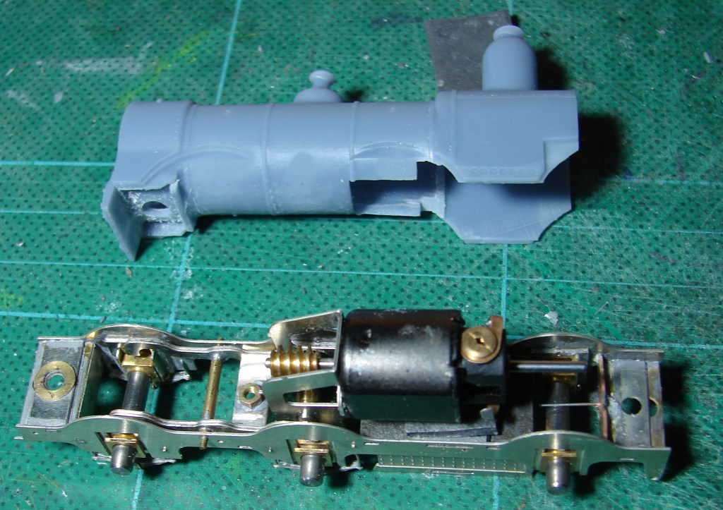
The chassis has the equalising beams and HLK RoadRunner gearbox built up and fitted. A steel wire has been soldered in as a sprung central pivot to give the crew a more comfortable ride. The grate area has been filled with sheet lead contributing a fair bit of weight. The rear motor shaft still needs to be removed. There will be some scope to add weight round the motor and above the wheels at the front of the rear splashers, as well as in the domes, smokebox and boiler. Seen are the fixed cutouts for the splashers and the additional cutouts needed for EM Gauge wheels which of course are inboard of where they should be. There’s plenty of room for the M1220, but only with the ends filed off the protruding motor fixing lugs. The centre bearing hornblocks and gearbox bearings had to be drastically thinned to get the 0.5mm side play required for a 3’6″ minimum radius curve.
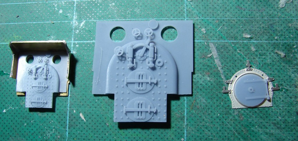
On mature reflection (in conjunction with someone who should know), the regulator has been moved to the middle and two gauge glasses fitted, one a mirror of the other. Whether they should have guards in 1884 is moot. On the left is a JH Beattie version of the revised backhead test fitted in the JH Beattie cab. In the middle the same in 7mm scale, printed with a view to encouraging a friend to build a 7mm scale Lion. On the right a nickel silver version of the smokebox front with handrail and lamp iron rivets set using a less pointed punch in his GW Models rivet press – with that it was much easier to centre the tool in the half-etched holes, thus ensuring that the embossed rivet is accurately placed.
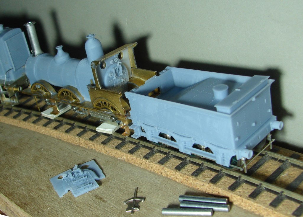
Steps assembled and fitted, and the rear splashers now soldered on. Quite fiddly, but no problems other than the slots being a fraction too wide. So far only 188C multicore solder has been used, carrying the solder to the job to burn off the unwanted resin flux in the process. The forward steps were a later upgrade to the Lions. Rather than cut the second shaft off what turns out to be his only M1220, He ordered an HLK 1219 coreless motor, and removed the M1220 so that the loco could be posed with the backhead in place. The motor is further forward in the Vesuvius and there might therefore be scope for a flywheel needing at least some of that second shaft. The reverser lever has been assembled (foreground). Height of top of the chimney from rail height is 54mm which is a scale 2″ greater than the LSWR loading gauge of 13′ 4″.
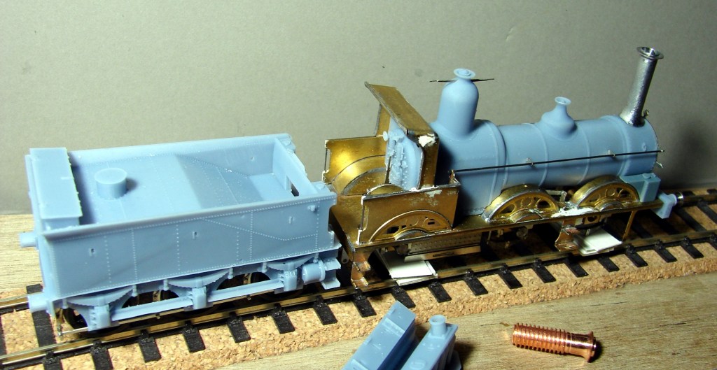
Handrail and etched handrail brackets fitted and 0.5mm steel wire loose fitted to confirm alignment (0.35mm wire looked too thin). In this photo something has been fretted out that looks like a reversing crank and rod between the leading wheels, in this case soldered to the outside of the narrow EM frames. The assembled reversing lever has also been soldered to the inside of the splasher in the cab. If this was 00 gauge there would be a temptation to solder it to the top of the splasher in correct alignment with the firebox sides. The cab has also been soldered in and some white Milliput used to fill some gaps, hollows and scrapes. The handrails have been fitted in the slot formed at the rear of the cab splasher and secured with the Milliput. Unfortunately it was very slow to go off and took a week to harden so suspect it’s actually ‘dried’.
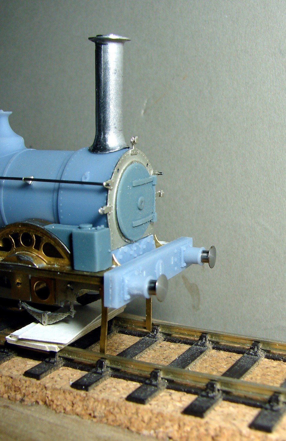
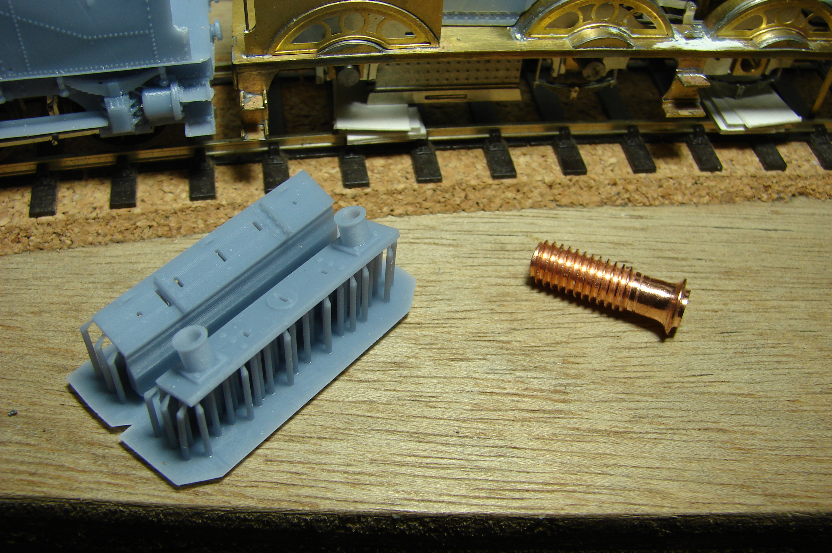
As usual it’s a photo (not the mk1 eyeball) that highlights that the smokebox door might not be fully home. 3D printing the buffer beam presented a problem in that it has two fair faces opposite each other, one of which must perforce be peppered with supports. Steve’s solution was to print it in two halves with a knife edge support at the bottom of each support and the fair faces printed at 20°. Both halves had to be thinned to compensate for ‘additive kerf’. A nice sliding fit was required for the AG buffers the shank of which was 3/32″ or 2.4mm. The housing was printed at 2.5mm diameter internally and that gave a perfect fit, but that took a couple of iterations to get exactly right. In the process Steve has been able to thin the walls of the housing to a nominal 0.34mm. As before the supports were added via Blueprint Studio and it was sliced in Anycubic Photon Workshop.

Also seen is his attempt at a copper capped chimney. Not being a GWR modeller Steve had no idea how nasty copper was to machine, but with files and cordless drill he eventually got somewhere close. The later Beattie chimney had a sloping top to the flange unlike the earlier ones, and Stour would have had that later chimney. Steve needs to cut chimney and cap square losing 1.5mm of height in the process, and that will be his next task, followed by painting wheels and frame LSWR Umber ready for assembly.
March & April 2026

March & April 2026

David’s Open Day in April featured both Nethercreech Junction and his new creation Lyme Regis. Some photos taken by YMRG members of Nethercreech Junction follow:

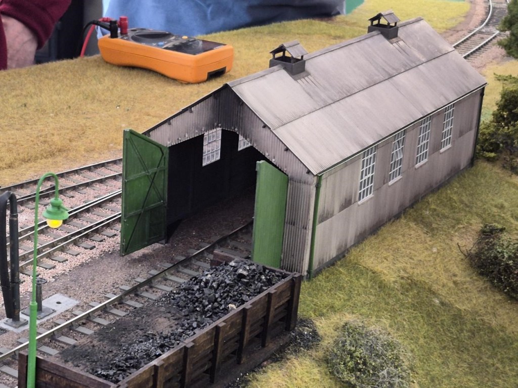
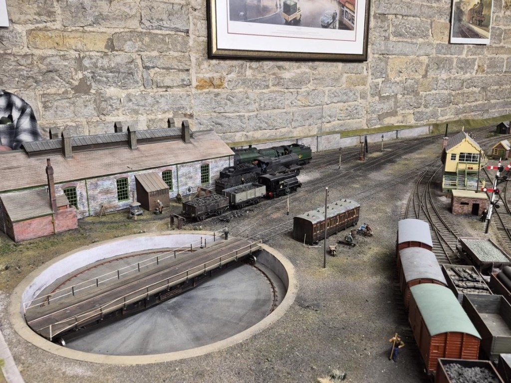
NetherCreech Junction Loco Depot
NetherCreech Junction Looking South
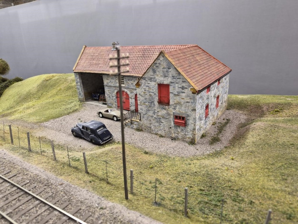
A Model of the Barn that Houses Nethercreech Junction and Lyme Regis painted in Estate Colours with Ivo Peters’ Bentley outside – as it really was on the Open Day!
Looking North towards the Level Crossing

And now two views of Lyme Regis. Member and retired architect Allan has been responsible for the buildings and excellent renditions they are too:

Finally, two further cameos at Lyme Regis:

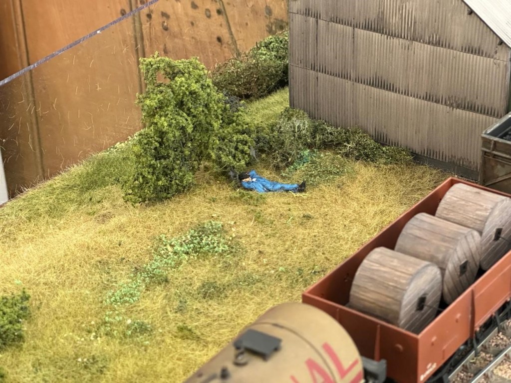
Looks like a nice place for a snooze.
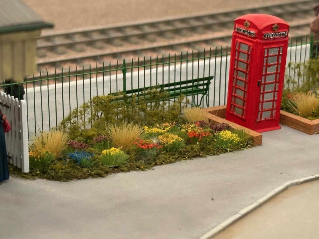
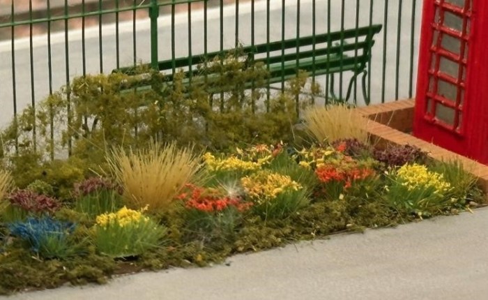
Is this the best flower bed on any layout in any scale anywhere?

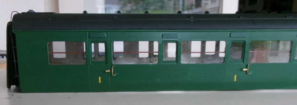
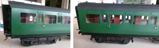
Pete C reports: The Maunsell coaches that the club bought from the estate of Simon K have had a few modifications and some repairs, one being a new bufferhead which had fallen off from a whitemetal buffer. A piece of brass was filed to shape and a spigot soldered in a hole in the buffer head to attach to the whitemetal housing. He then noticed that the cowling over the droplight windows had never been fitted, these were cut from plasticard and painted (luckily Railmatch paint was the same shade) then stuck on with thin superglue. The other noticeable missing items were the very prominent wooden handrails behind the corridor windows. Copper wire was painted and fitted to clips made from plasticard. The remaining job is to drill some holes in the solebar to secure the footboards properly.
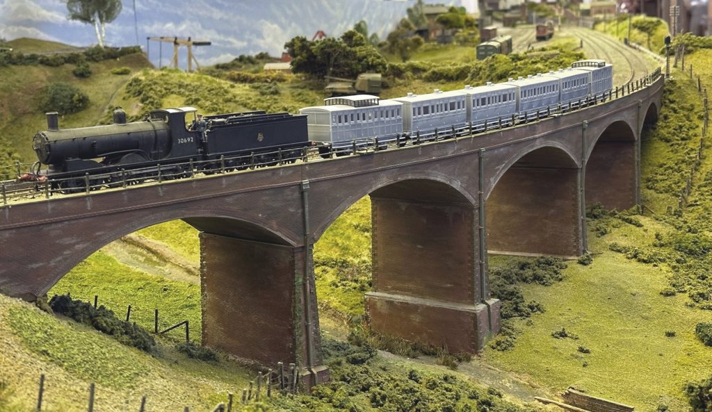
Steve has been steadily working through the many issues of 3D printing his LSWR coaches from the 1860s (in 4mm scale EM Gauge). Courtesy of Keith, not the Downton Train Crash formation of 1884, but a very close coupled rake of 3D printed coaches of all the required types crossing Bob Alderman’s viaduct on South Junction. The 1864 Passenger Brake is leading two 1865 Thirds, an 1862 Second and 1862 First, with the 1859 Passenger Brake bringing up the rear.

The Black Motor 30692 is the least inappropriate engine that he currently has to haul them, although it is at least a Sal&D engine. Built from a Jidenco kit by someone who had some idea of what they were doing and bought secondhand. The somewhat undercooked Jidenco 00 Gauge underpinnings were replaced using Persy chassis kits built to EM Gauge. Those familiar with Steve’s projects will guess that this could be made more complicated than it really needed to be: https://yeovilmrg.org/black-motor-re-chassis-in-em-gauge/

Finally Part 2 of the Big Bertha saga that could be a trilogy if it includes fitting the brake gear.

January & February 2026

January & February 2026

Jim has concluded that CS2 is not the best place to try and make something of the ‘Aberdeen White Elephant’, otherwise known as the ginormous 2mm finescale fiddle yard that I carted down from its namesake in north east Scotland (ie Aberdeen!) in the summer of 2019 and done little with since, due to (a) Covid and (b) his house move to Exeter in 2022.

Despite the loft in his bungalow having insufficient headroom to stand up in, and the loft hatch being unable to accommodate 8ft long baseboards, he has decided that he can make a better fist of it there than he first thought, and it will remove the need for regular 100 mile return trips back to Somerset.

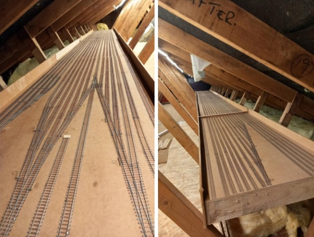
Accordingly, he ‘bit the bullet’ a few weeks ago and carefully cut a few millimetres out of all the rails (36 at every baseboard joint with 18 parallel storage roads) followed by gently sawing through the MDF baseboard top to convert three baseboards 8ft long into six baseboards 4ft long. All six boards are now up the loft at home and, simultaneously, I am adding raised flooring to gain access right down the length of one leg of the roof space. Below is a picture showing four of the boards, with two more to be added at the far end, before a corner is added:

The second picture is taken from the other end and shows the fifth “half-board” added and more of the new flooring to the left. Of note is the relatively little vertical leeway Jim has to insert cross struts to support the boards more positively.
In May, the 2mm Scale Association is having its usual show at the Derby Conference Centre and this year it is all weekend, rather than just Saturday, and the star of the show will be Dunallander, which this fiddle yard was originally built for. Included in the van from Aberdeen this time will be the Perspex sheets that cover the fiddle yard boards which Jim forgot to collect in 2019!
A reminder that the scenic side of the layout has yet to be started but, in comparison, will be very simple and comprise a double track main line, with overhead 25kv catenary (!) and mineral exchange sidings and a branch leading to Littleton Colliery, near Cannock in Staffordshire. In contrast, the Grampian Area Group of the 2mm Scale Association, who was persuaded to save the scenic side of the original layout, have strived to construct an almost exact copy of Dunblane Station and its immediate environs, involving many, many buildings – see photo above at the Elgin Show. In contrast Jim’s rendition of Bungham Lane, Penkridge only needs one building, the junction signal box!

February saw Part 1 of the Big Bertha Repair ending on a cliff hanger see the link below:

Next up Steve’s Lima Class 156 Upgrade incorporating his own and Hurst Models resin 3D printed parts:

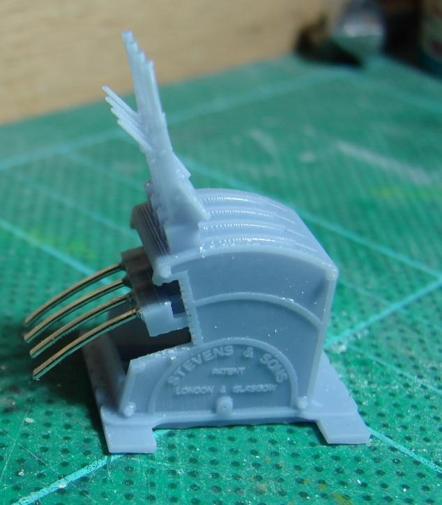
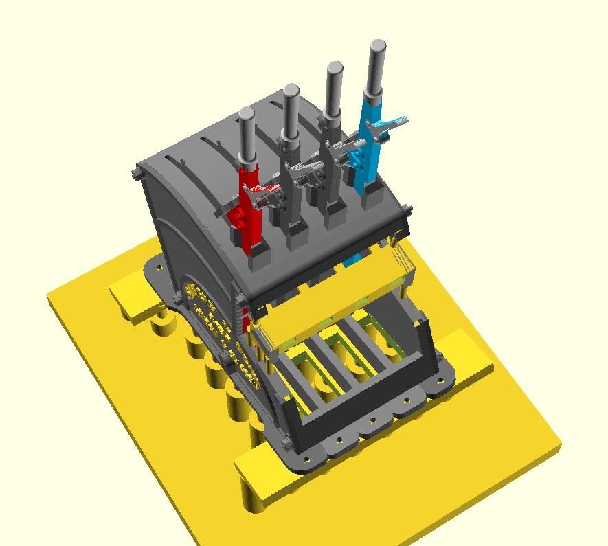
Steve is modelling Verwood in EM Gauge, and needed a Stevens style lever frame for the box plus a Stevens style Knee frame for the ground frame that was at the West Moors end of the loop. He’s 3D modelled these in QCAD and OpenSCAD and is 3D printing them in 4mm and 7mm scale on his AnyCubic Photon Mono 4K in AnyCubic ABS-Like Water Washable Resin 3.0. Both can be configured to have LSWR or SR style plates and with any number of levers. Could the models be 3D printed though?

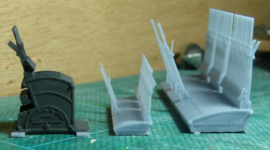
This is a 7mm scale version of Steve’s 3D printed LSWR style ground frame for Verwood with some overly thick tails fitted to the locking frame. The clearness of the text suggests to Steve that his BR(S) smokebox plates (with curly 6s and 9s) could probably be printed vertically rather than on the bed allowing me to batch them up on a raft and remove and prepare them as required.

A test print showed that when tilted up on supports for 3D printing, the void under the tails needed to be more realisticly modelled (almost empty bar framing) so that it could drain of resin and water during washing. Win-win!

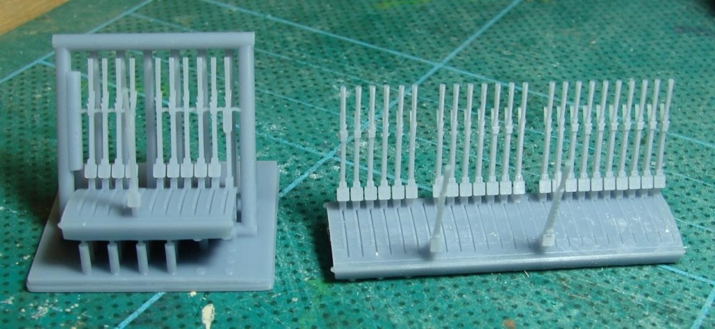
On the left a reject ground frame with coat of Humbrol Dark Grey to bring it to life. Also ‘Privett’ LSWR era frames in 4mm and 7mm scale with just the FPL levers reversed, as these frames were for most of the day waiting for something to happen. These sort of frames were not untypical of the Meon Valley and other somewhat overbuilt lines of the same period.

On the left a lever frame for Verwood in the final version of the support cradle. As with the ‘Privett’ frame on the right, what should have been the only FPL is pulled awaiting the next train – that was a mistake as it should have been Lever 4! The Privett frame was fairly easy to release from the final version of the support cradle with nicely aligned levers. It looks like some of the supports for the Verwood frame went AWOL but recovered just in time! There were a lot of iterations of the support cradle before it worked reliably every time.

November & December 2025

November & December 2025

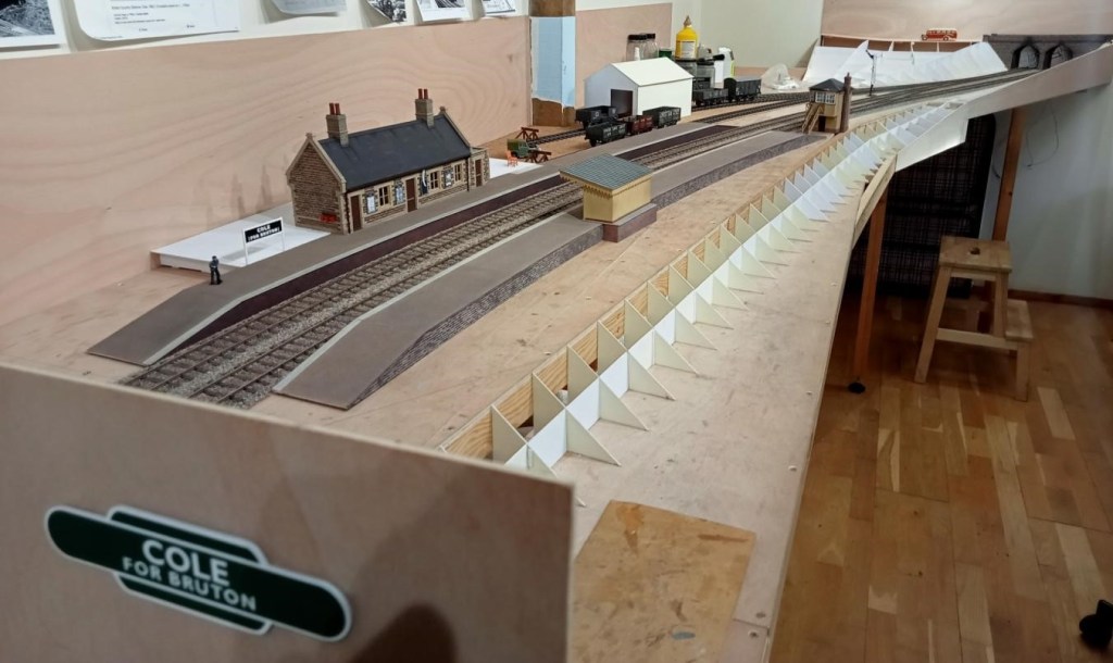
Allan is making good progress on his 7mm rendition of Cole. Platforms have been started and landscape formwork started. The platform surface was finished using fairly fine emery paper dusted with weathering powders (and brushed off outside as the stuff gets everywhere!).

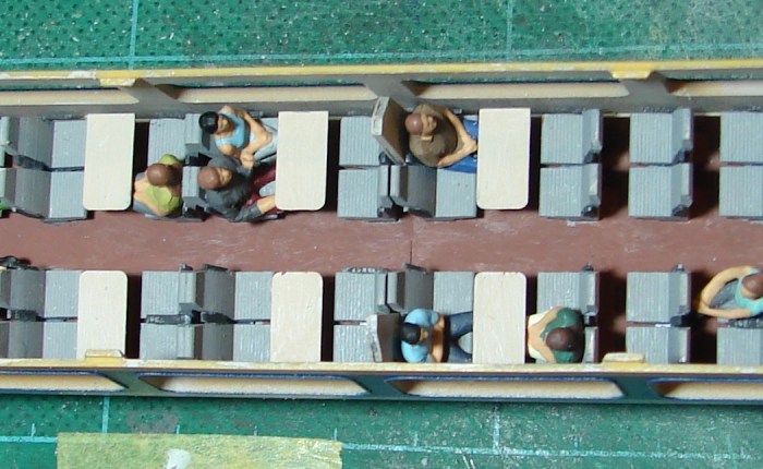
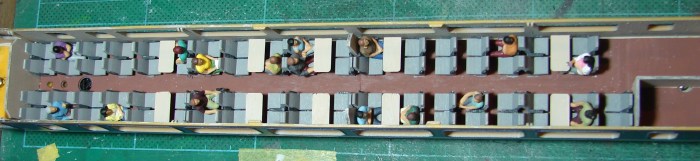
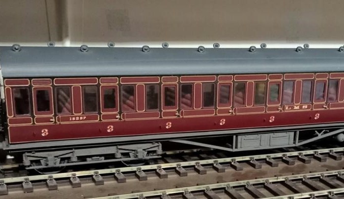
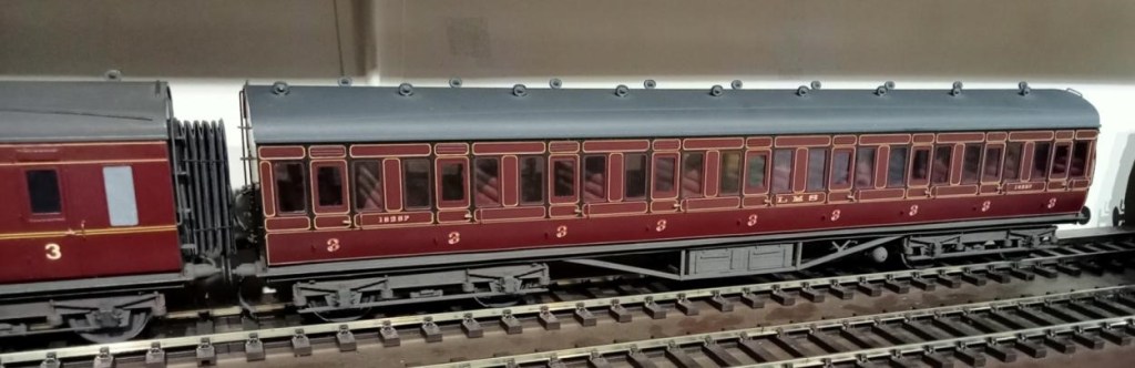
This is a recently acquired LMS Period 1 all third coach built and painted by the Sidelines man himself Malcolm Binns. Jim couldn’t resist it even though outside his period as the lining is outstanding. Unfortunately Jim had to refix the seating and entirely reglaze it – old model, old glue!

Plan of Proposed Layout

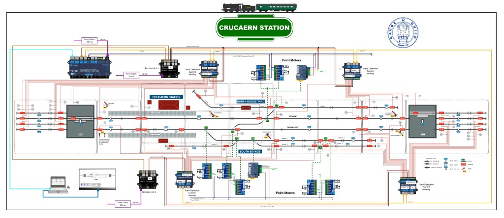
Andrew has been busy planning and ordering parts for his O gauge layout Crucaern Station (Anglo Saxon for Crewkerne. “Cruc” is hill and “aern” is a place or building). He’s taken delivery of a large box of points and track from DCC Train Automation.

iTrains Control System Diagram
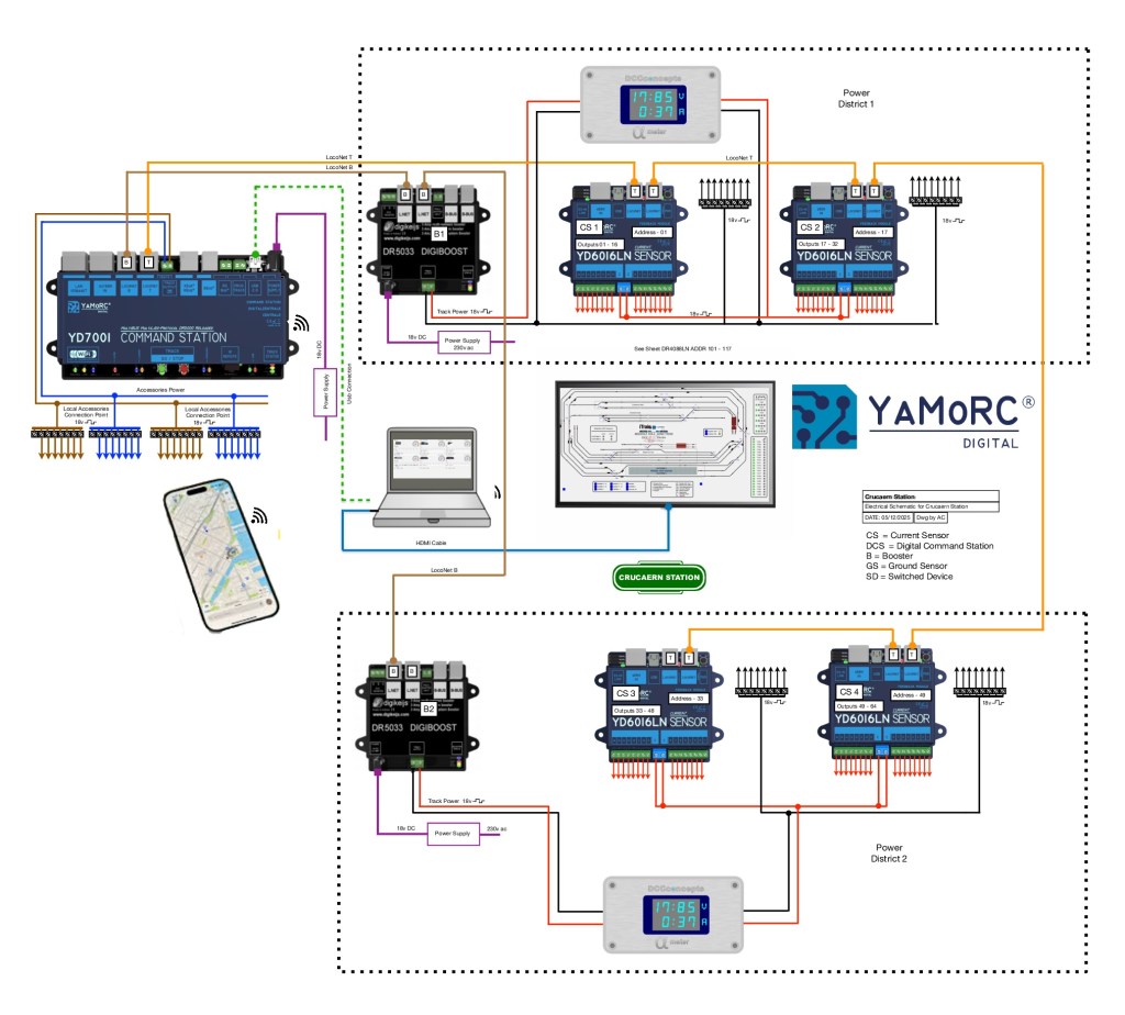
iTrains Schematic showing where everything needs to go

Below a few words to describe what should happen.

System Description for Crucaern Station O Gauge Layout
The control system for the Crucaern Station layout is built around the YaMoRC YD7001 command station, which provides the DCC command signal, LocoNet communication, and accessory power for the layout. The layout is divided into two electrically isolated track power districts to improve reliability and fault handling. Each power district is supplied by its own DR5033 booster.

Track Power Distribution
Track power within each district is delivered via dedicated red and black wiring from the DR5033 boosters. The two power districts are electrically independent, allowing one district to continue operating if the other experiences a short circuit.

Booster Communication (LocoNet-B)
The boosters receive their synchronised DCC control signals from the YD7001 via brown LocoNet-B cables. These connections ensure all boosters operate consistently and maintain a stable DCC output across the layout.

LocoNet Communication Network
A network of orange LocoNet cables interconnects the command station, feedback modules, boosters, and display units. This network carries system-wide communication including block occupancy data, device status, and accessory control.

Block Detection and Feedback
Each district includes a combination of DR4088LN-CS and YD6016LN feedback modules. These units provide current-sensing and ground-sensing block detection, reporting the presence of trains to the control software via LocoNet. This enables automated operation, route setting, and visualisation on the layout mimic panel.

Accessory Power
Accessory devices such as point motors, relays, and signals are powered using a separate accessory DCC feed from the YD7001. This keeps turnout and accessory operation independent from the track power feeds to ensure stable running.

Power Meter Displays
Digital display units within each power district monitor voltage and current draw in real time. This provides clear visual status information for operators and helps diagnose faults quickly.

Control Interfaces
The YD7001 connects to a computer for layout control software and to wireless devices such as smartphones and tablets for handheld throttle operation. A screen-based mimic panel provides a graphical overview of the entire track plan, including live block occupancy and turnout positions.

Technical Overview
This layout is divided into two power districts, each managed and monitored to provide reliable DCC operation, feedback reporting and accessory control. The wiring scheme uses a combination of power buses, boosters, feedback modules, point motor drivers and signalling components, all coordinated through the YD7001 command station and LocoNet.

Power Distribution
A pair of red and black solid lines represents the main DCC track bus. This bus supplies traction power to the entire layout. The bus is divided into two separate power districts, each protected and managed independently. Dotted boundary lines identify the equipment assigned to each district.
Boosters and Command Station
The YD7001 acts as the central DCC command station.
It provides:
Booster outputs (brown lines) feeding the DR5033 boosters via LocoNet B. Each DR5033 supplies regulated track power to its respective power district and provides short-circuit protection.
Auxiliary power outputs (blue and brown lines) used to feed point motors, accessory decoders and other low-current devices.

LocoNet Communication
All digital communication between devices is carried by orange LocoNet cables, linking the YD7001, boosters, feedback modules and accessory controllers into a unified network. This ensures reliable synchronisation of power management, occupancy detection and signal control across the entire layout.

Block Detection and Feedback
The track is divided into several blocks, each identified by blue labels.
Every block contains two feedback sensors, represented by red labels, providing precise occupancy detection. These sensors report directly to the feedback modules via LocoNet, enabling automated signalling, route setting and train monitoring.

Points and Signals
Turnout control is handled through green-labelled point motors, each connected to the accessory power bus and controlled via LocoNet accessory commands.
Yellow-labelled signals are positioned at block boundaries or key junctions. They respond to feedback events and route logic, ensuring accurate line-side indications for both manual and automated running.

Overall System Function
All components operate together as a coordinated digital layout control system:
– The YD7001 provides command, logic and accessory control.
– The DR5033 boosters supply isolated, protected traction power.
– Feedback sensors deliver block-level occupancy data for automation. Accessory devices such as points and signals respond intelligently to LocoNet instructions.
– LocoNet interconnects the entire system, maintaining consistent communication.
The result is a fully integrated DCC control environment supporting automated operations, realistic signalling and reliable running across the layout.

Andrew also informs us that there are only two boards left of Heyno Junction to wire up before trains can run complete circuits! [Ed. Something I can understand!]

September & October 2025

September & October 2025

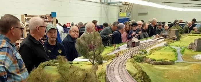
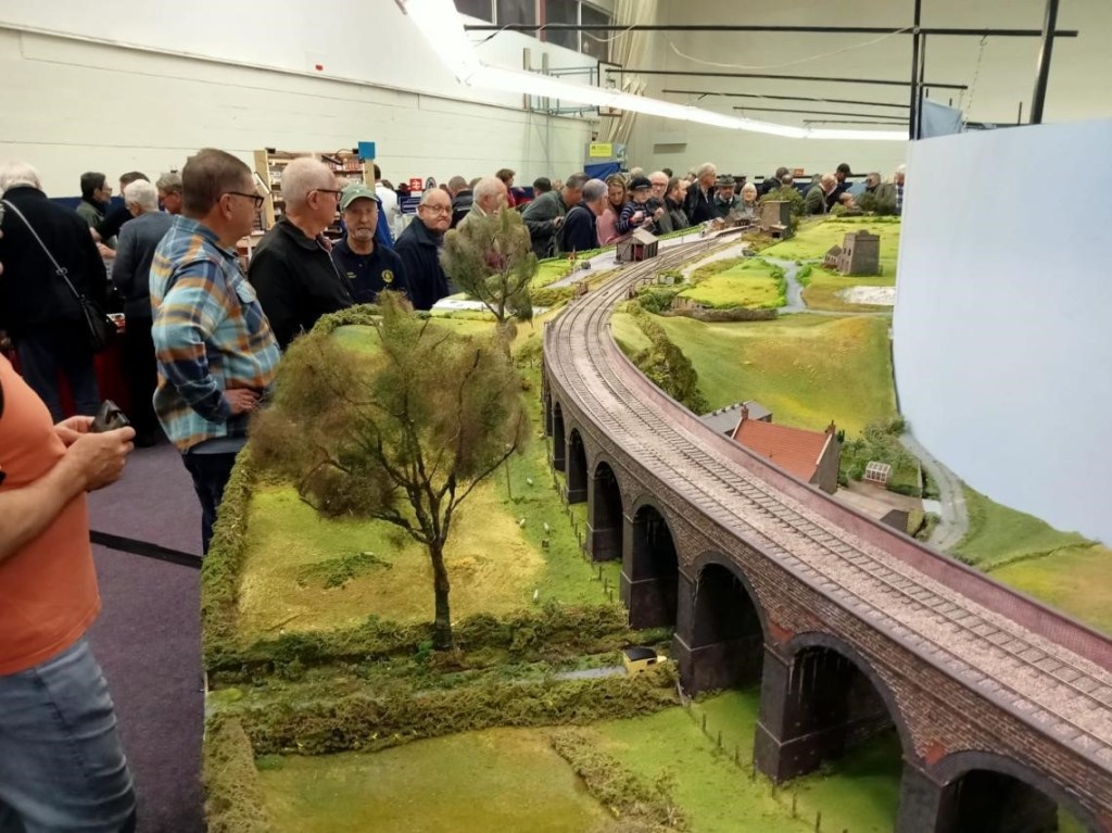
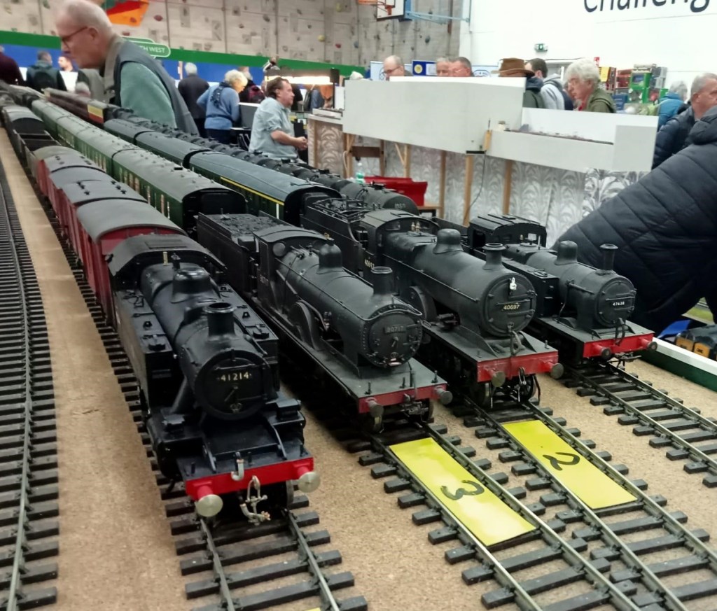
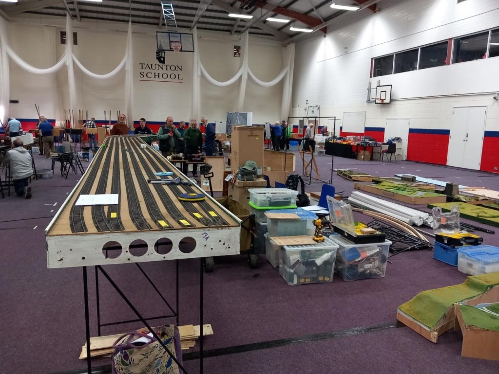
For the last few months most of the work at CS2 has revolved around getting Evercreech New ready for its second appearance at Taunton Railex. Happily its appearance was an outstanding success and the team involved should feel very proud and pleased, especially given the hard work involved. The Somerset Railway Modellers were brilliant hosts and Taunton School a superb venue with proper puddings. A few pictures from the event follow:

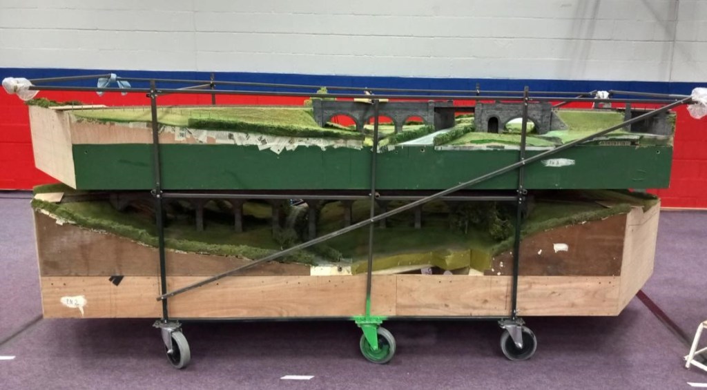
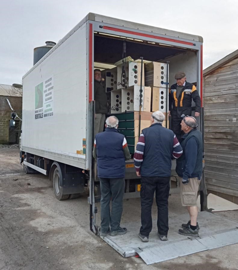
The infamous viaduct stillage (when loaded the size of a small car), with Prestleigh Viaduct on the bottom and Pecking Mill above. The castor painted green is key to the loading procedure – there are actually six castors on the stillage, and it has to be carefully pivoted on the outside edge of the tailboard on the green castor since the stillage is too wide to go in sideways.

This is why we do this!

The fiddle yard, with the operating area of other layouts behind.

Prestleigh Farm, which is unfortunately mainly hidden from the viewers by the viaduct, although Dave H constructed a high level background mirror to help with this. Next a few pictures taken during loading at CS2 and unloading at Taunton School:

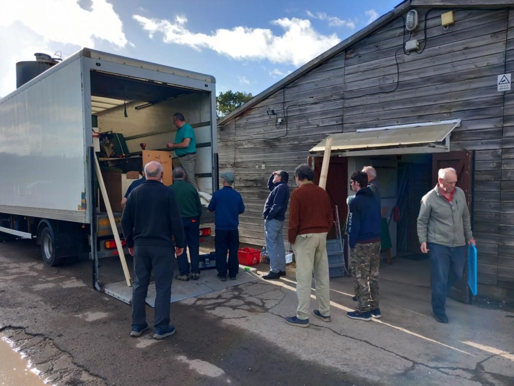
With more scenery than last time, will it all fit in the lorry? Maybe……

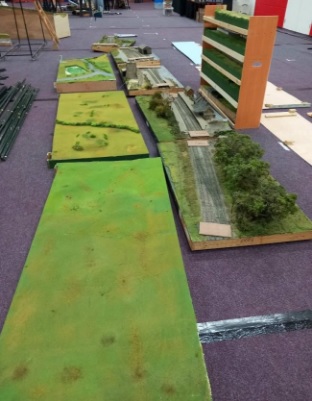
The the new landscape boards (left) and original station boards waiting to be loaded.

Early stages of setting up on the Friday with a good three hours to go before it will be ‘ready to run’.

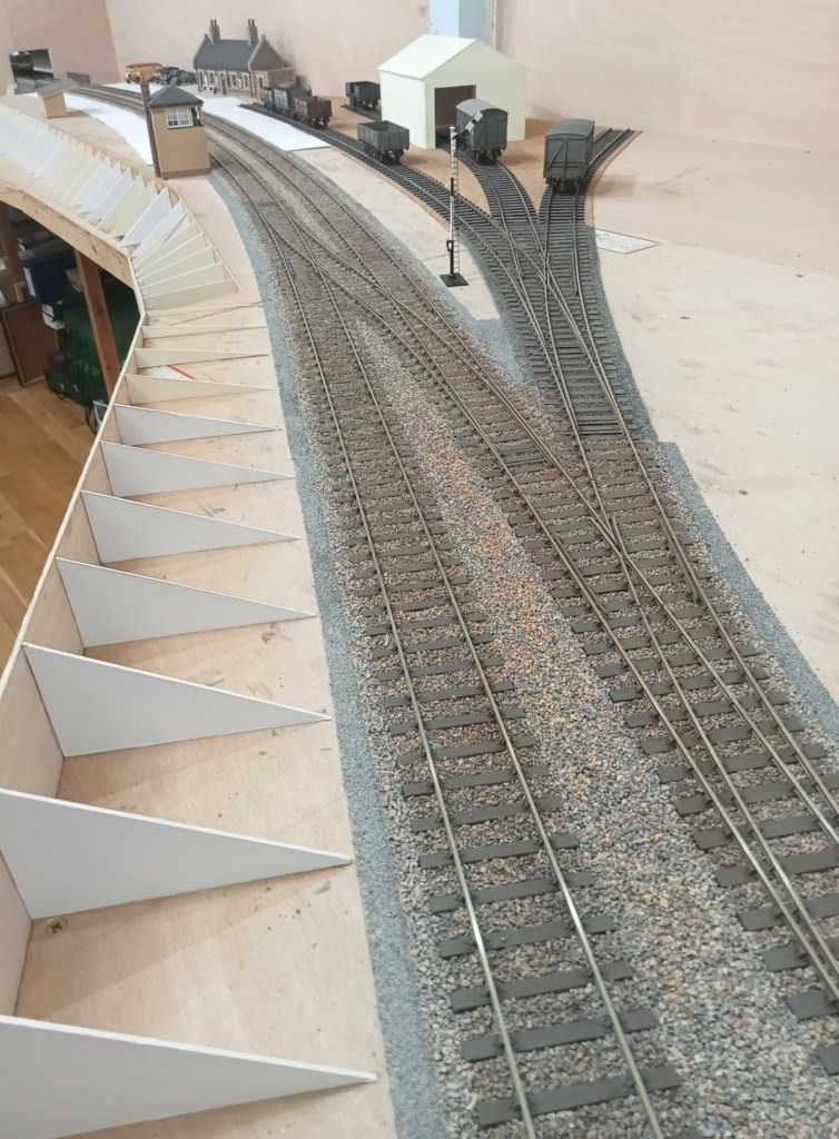
Meanwhile, In his large purpose built railway shed Allan has been working away at his new project, Cole (S&D) in 7mm Scale. The trackwork has been constructed from C&L components on plastic sleepers and the three way point was ‘particularly challenging’. [Ed. The ballast and colour of the sleepers I find pretty convincing, and doesn’t it flow nicely.]

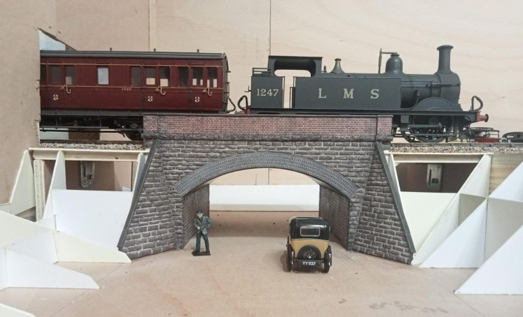
The bridge over the lane going up to Sunny Hill School. Will the Austin 7 need to reverse to make it up there? The arch was laser etched and cut by Mike of Jurassic Models.

July & August 2025

July & August 2025

The project that has gripped Jim over this period was improving an ex-LMS 4F 0-6-0 which he bought some while ago via the Gauge O Guild ‘Sales and Wants’ on its website. A kit of some description, it had been constructed in true ‘Tri-ang fashion’, with the motor/gearbox installed horizontally so the lower part of the boiler had to be removed. Jim managed to re-install this with the motor sited vertically in the firebox some while ago, but he has now got around to filling in the missing part of the boiler and remodelling the inside of the cab so a crew could be added. A false floor was constructed out of plastic card to match the level of the tender and a flap of very thin plastic card added to bridge the gap. Hopefully the crew won’t now fall out!

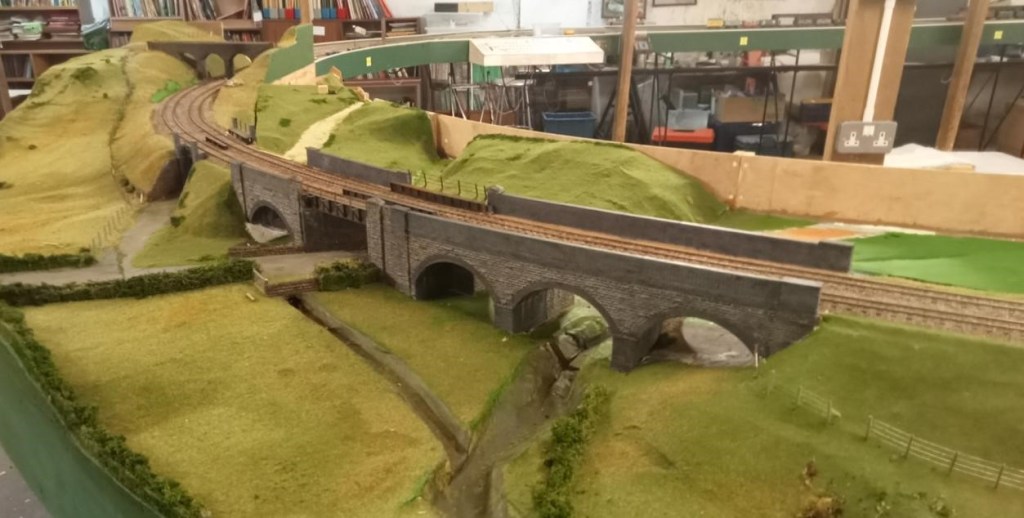
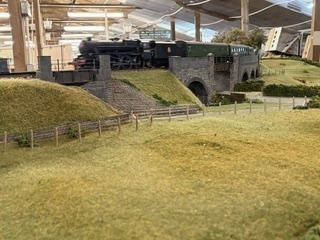
The main efforts in CS2 have been directed towards developing the scenery on Evercreech New ready for its appearance at ‘Rail-Ex Taunton’ in late October. At a recent visit to CS2, Allan took some pictures of the area around the two viaducts. As can be seen things have really started to come together on Evercreech New.

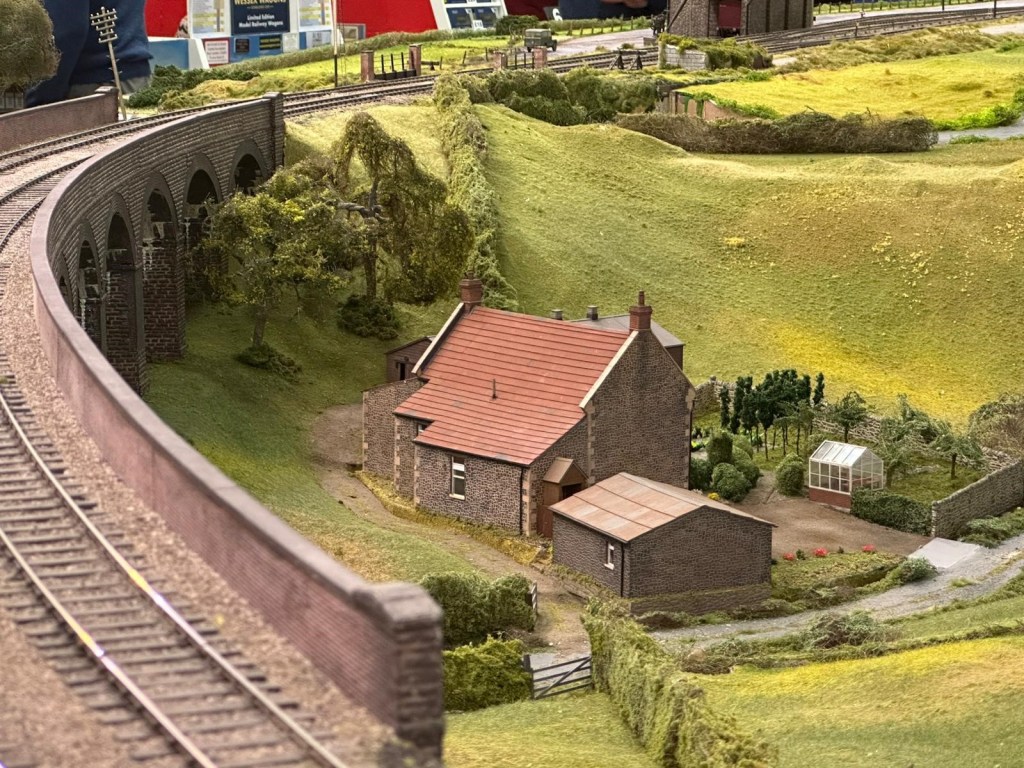
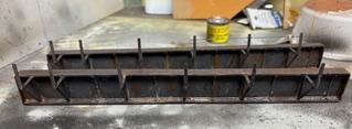
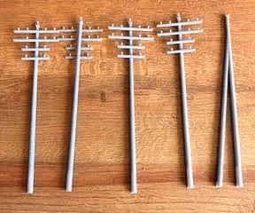
New bridge sections have arrived, made in a flexible ABS-like resin. They’re much easier to fit and are currently on the workbench getting some weathering treatment to help them blend in nicely. Over on the Pecking Mill Viaduct, the scenic team has been busy with the static grass, and the area is really starting to look the part. Fences and hedges have gone in too; which adds a lot of depth and character. Some very neat 3D-printed telegraph poles have been made up. These are destined for both the Pecking Mill section and the station area, and will add another great detail once in place.

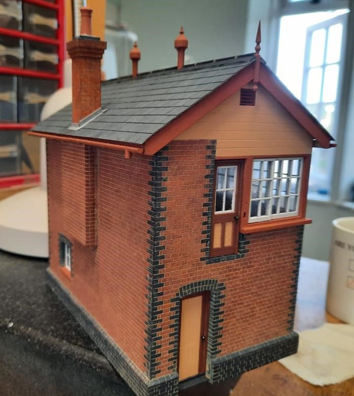
Dave H has been building a signal box from a laser-cut kit and now has the fun of the interior, using the etched brass kit from Severn Models

This reminded Jim of the signal box he had constructed some while ago for Littledean, from an LCut Creative kit, that included a full interior.

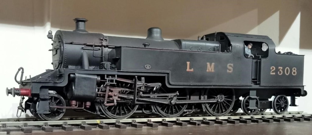
Allan has been beavering away at his 7mm rendition of Cole, and recently added an LMS 2-6-4T to his loco roster. Made from a Gladiator kit, the Fowler 4P has always been Allan’s favourite tank engine. He recalls seeing them in Manchester in his youth, but it is unlikely they ever appeared on the S&D. But what the hell it’s beautiful! [Ed. who wonders what that chimney is going to be when it grows up.]

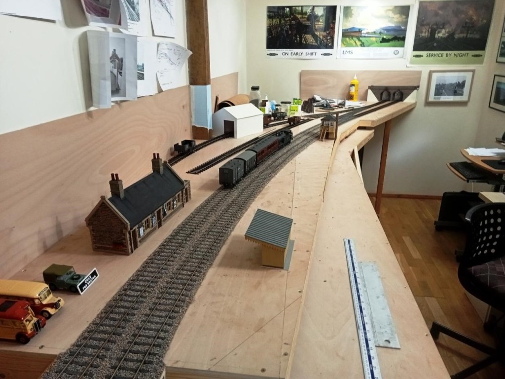
This is where Cole stands currently. There will be a hole in the shed wall beyond the overbridge so that through trains can run on into the garden – not much point in modelling a through station otherwise. [Ed. 0 Gauge in the garden – where there’s room for it – what’s not to like?!]

May & June 2025

May & June 2025

Although not quite finished, in May David S held an Open Day to show his superb new 7mm layout of Lyme Regis in its entirety.

Alongside his work on Lyme Regis, Allan has continued work on his new 7mm layout and built the platform shelter for Cole (S&D) Station. Allan didn’t want to model the sag in the roof. Those props may well have been added to combat the sag on the real thing. Below is some additional rolling stock for Cole.

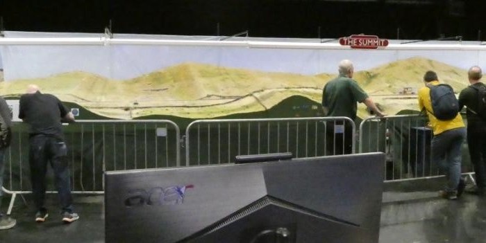
Since the last blog, The Summit has been exhibited at the two and a half day Bristol Show at Thornbury and acquitted itself well. Glimpsed in the background the scenic boards are back in their stillages and all hands have been diverted to Evercreech New which is due to appear at the Rail-Ex Taunton in late October.

Pecking Mill Viaduct is a complex structure and a curve has had to be introduced to it so that it fits on our layout. Because of the curve the 3D printed girders for the skew bridges cannot be quite parallel or exactly the same length. All this has led to a potential lack of clearance if the girders are not precisely placed. There is a timber walkway outside the girder and the railings for those pretty much align with the outside of the piers leaving just enough clearance for model coach and loco overhangs. The girders may be very slightly outboard of where they should be as a result. The girders were printed in two halves, the farm bridge girders being similar but shorter, and it was vital (there was some confusion), that only the long half girders were used on the A371 bridge. (Ed. We kid you not!)

This wing wall was also replaced with an embankment – because there never was a wing wall there! The painting of the viaduct is complete, and looks good. Once the bridge girders are in place work on the groundwork, fencing etc. can start to make the place look real. There’s a good base layer of grass on some of it, it just needs a bit of variation, and longer grass on the embankment inside the railway fence. The road needs a camber on it and some attention to texture and colour, and there’s a small stone bridge over the stream needed too. Dave H was trying to explain Pecking Mill Viaduct to his father (he was a civil engineer). He thought it was something we’d made up as a modelling challenge, not a real place!

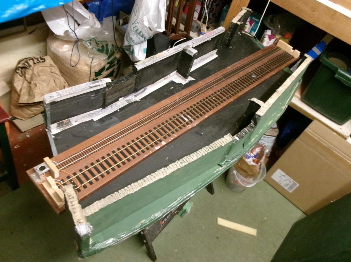
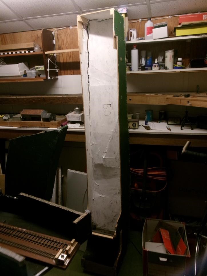
The scenery for The Summit was quite deliberately built ‘light’ as it only needs to hang off the rigid backbone boards that carry the track. This makes it vulnerable to damage as it’s ‘persuaded’ into and out of the stillages. Seen here, repair work is in progress with reinforcing of the tunnel boxes with paper mache joints. The scenery board has had the scenery detach from the frame for about 50%. Again paper mache, i.e. several layers, should be enough plus a couple of wood blocks glued in.

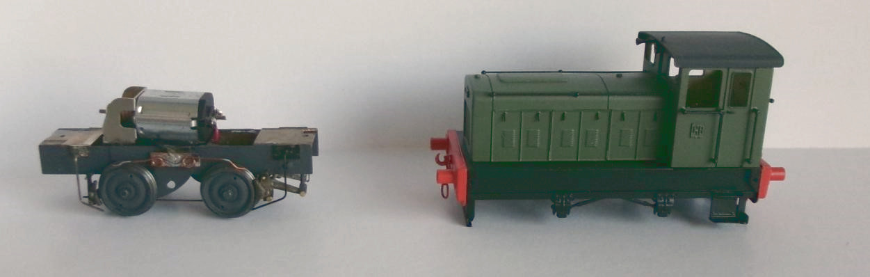
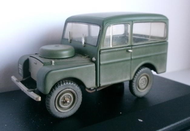
From Pete C, a 4mm Scale EM Gauge Ruston 88DS built from a Judith Edge kit, and perhaps more interestingly a weathered 7mm Scale Tickford bodied Land Rover intended for The Summit. These Tickford built Landies were marketed as a ‘Station Wagon’. They were better equipped than the standard Land Rovers and thus attracted Purchase Tax limiting sales. About 900 were produced, most were exported and few survive.

March & April 2025

March & April 2025

Dom has been making progress on both the scenics and fleet at 00 Gauge Coombe Town.

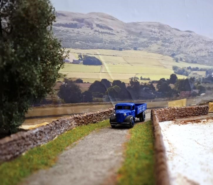
The remaining road surface has been added forming a nice country lane.

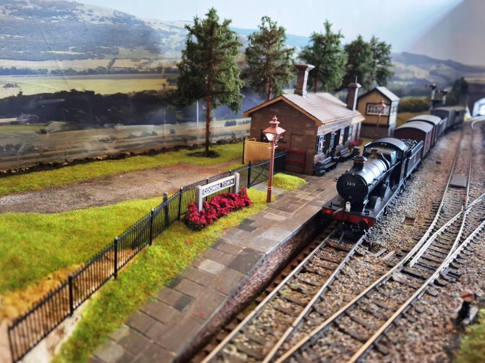
The station forecourt and more grass has been added as well as planting on the platform. 3212 has now been fitted with sound and a firebox glow adding a tender locomotive for the goods roster.

Hinted at in a previous post Dave H’s fabulous scratchbuilt 990 Class (0F Gauge) had indeed had a close (and abrupt) encounter with a floor. He had spent a couple of days with Dave S in North Wales and took his mangled 990 with him, which had been sitting in a “too sad to look at it” box for a year.

Dave S took it out of its box and set about unbending it during an afternoon with the aid of a blowtorch. In the end he had to make and splice in a new piece of footplate, but managed to get the S shaped buffer beam straightened out, and some other nasty dings and bends straightened while Dave H watched. Every now and then Dave S would say “Look away now, Dave” and there would be an almighty thump. Something to do with techniques for restoring vintage cars, I believe! Dave H took heart watching all this and took the big Z bend out of the front frames with some pliers.

Anyway, the photo shows the results. So a big “thank you” to Dave S, who persuaded him that it can be fixed! If there is a silver lining to this cloud, then the necessary repaint could be partly justified because the alleged Halfords etch primer didn’t etch, so the paint is not very fond of the metal. It won’t be ready for Bristol, sadly, but maybe it will run on The Summit another day.

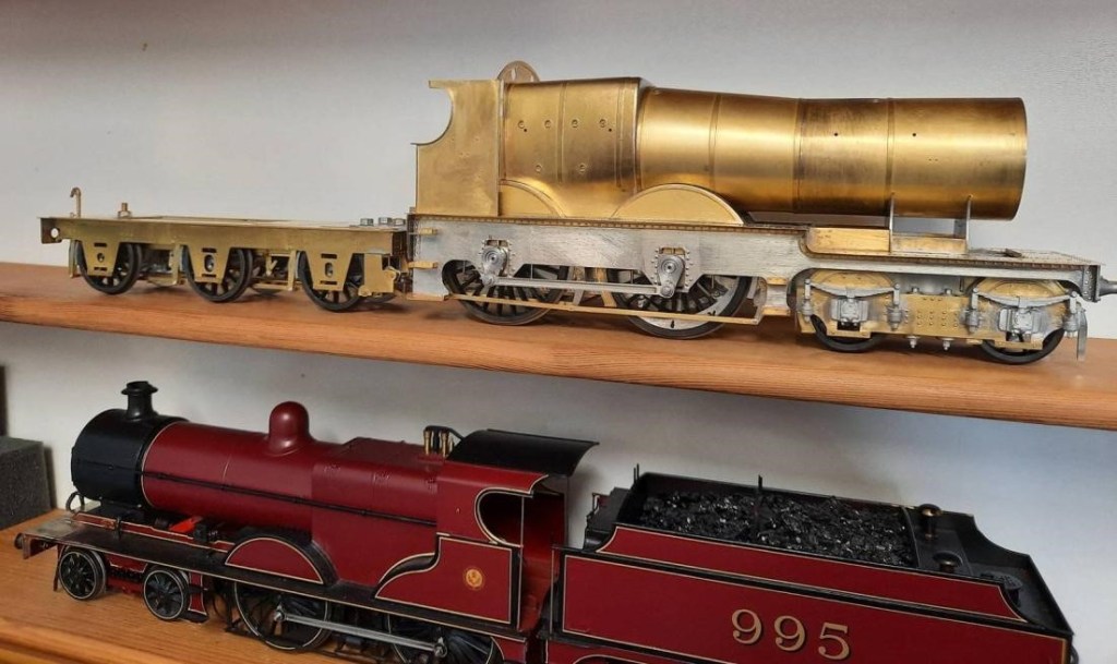
Dave H has also been working on City of Gloucester over the winter – the bones of it are done now, just detailing to do. Fitting the upper works to the footplate was very fiddly but he got there in the end. The ‘City’ is a much smaller looking engine than the 990, although I think the heating surface in that fat Std. 4 boiler might be greater. The ‘City’ didn’t have to get over the Settle and Carlisle, though, just trundle along on Brunel’s billiard table! [Ed] There was a definite lump in the green baize between Tiverton Junction and Exeter, even if these engines never made it as far as the infamous Devon banks!

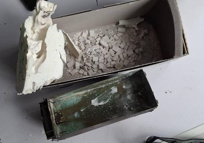
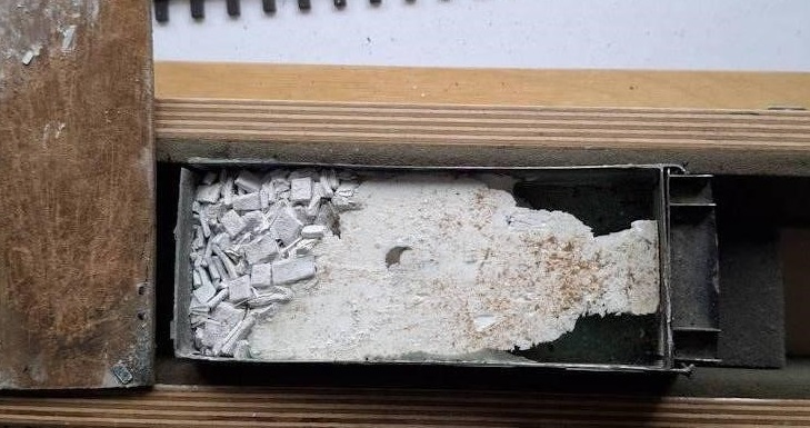
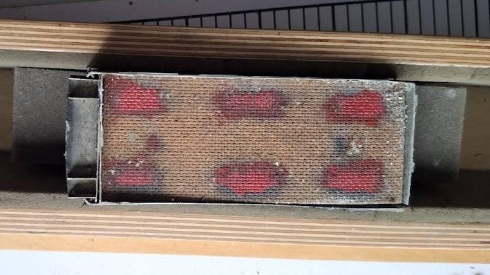
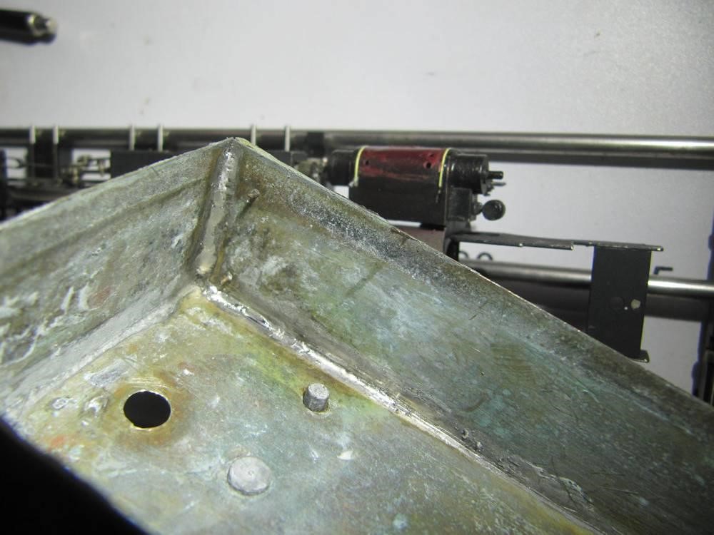
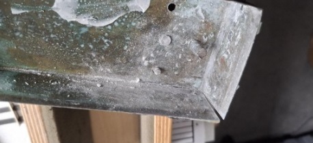
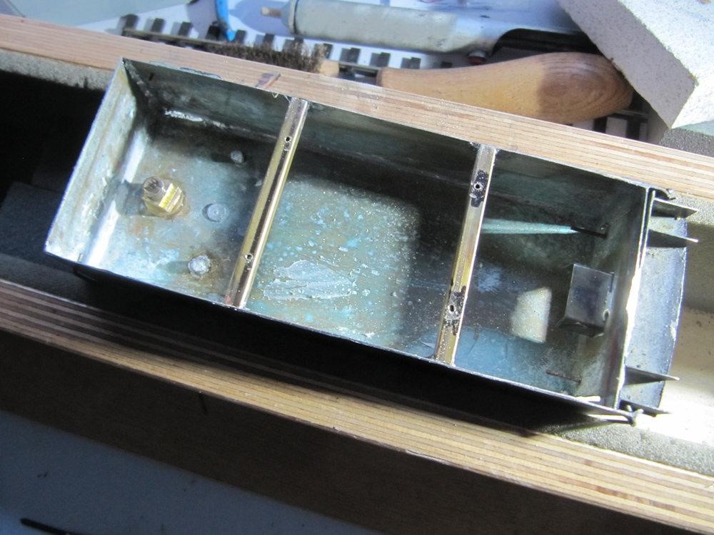
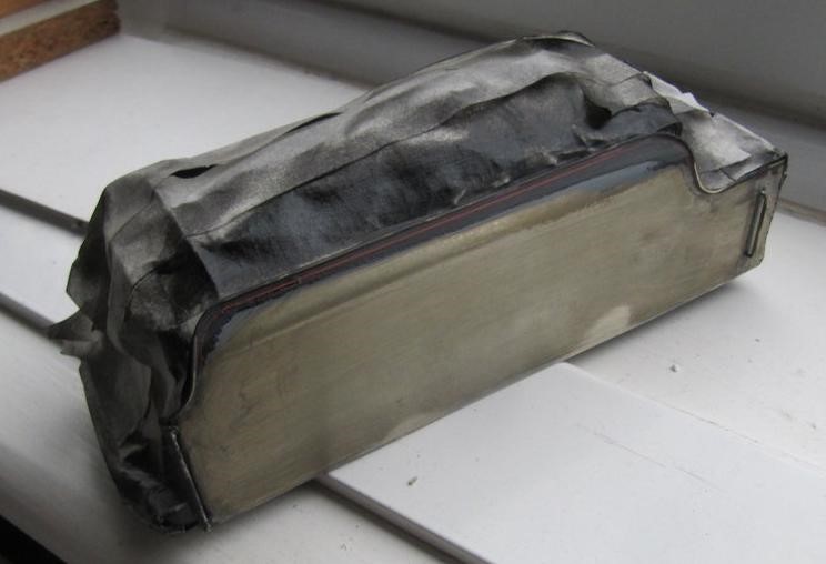
Dave S (master of the hammer) was asked if he might be interested in fixing a Black 5 tender with a split corner. Unfortunately Dave did not take an initial picture of the tender. It was an old model and it was built not to be taken apart. The tender rattled when shook but there was no way to get to the inside. The first job was to remove the tender body from the chassis. A thin fine toothed back saw helped in that process. The first three pictures show the contents of the tender body. I’m not sure what the white mineral was but there was a lot of white bath sealant in there too.

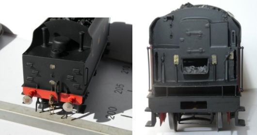
After cleaning up, we arrive at the re-soldered joint and the split in the hopper before.

The next problem was how to attach the tender body back onto the chassis. Two hollow square section brass stretcher bars were soldered across the tender body base.

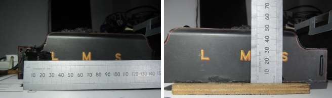
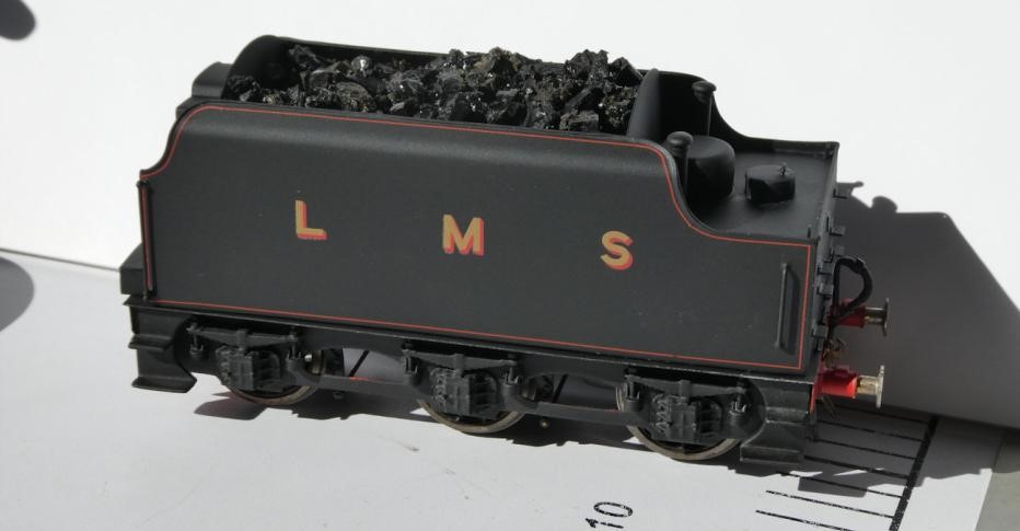
The heat from the soldering process burnt the paint on the outside of the body. As some of the original varnish had already come off, a repaint was in order. Transfers for the letters L, M and S along with some thin red lines for the edges of the tender body were ordered from Fox Transfers. These pictures show me measuring the positions of L, M and S to ensure they went back in the same position as received. [Ed] Looking at that ruler this model must be in 7mm Scale 0 Gauge (for those wondering).

The tender body ready for painting. Dave needed to mask some small etched plates on the tender body so that they did not get painted. He used Phoenix Precision PQ7 Superacrylic Masking Fluid. He’s sorry that he did as he found it to be awful stuff to remove – never using that again. Sue then gave him some Pebeo Drawing Gum that she used. This he found to be totally acceptable on further masking he had to do. [Ed – This is exactly how marriage should work!] The body was given a coat of light grey primer followed by a few coats of gloss black (as recommended by Fox transfers). Once dry, the transfers were applied and then given a few coats of matt varnish – part of the owner’s request.

The last pictures show the finished item looking good again. It has been returned to the owner who is delighted with the repair.

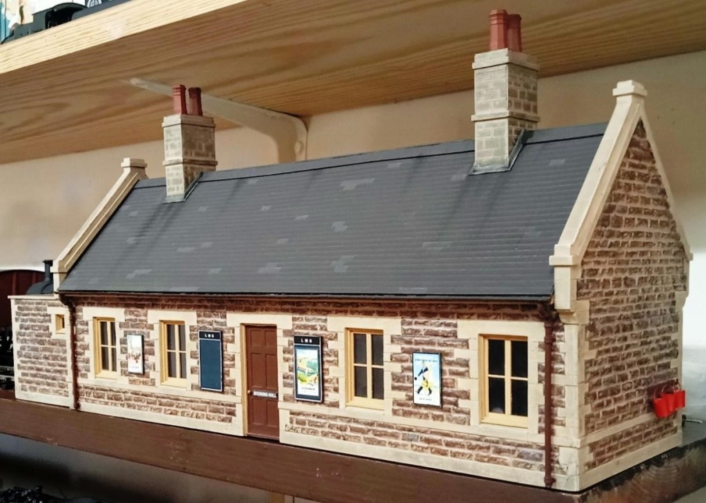
Allan’s superb completed model of Cole station in 7mm Scale. The wires sticking out are for a light fitting. Allan thinks that perhaps the roof could do with a little more weathering. Purists [Ed. That would be me!] are going to dispute the LMS colours but, as with the signal box, he would find it difficult watching his LMS trains passing through the station painted in SR colours!

January & February 2025

January & February 2025

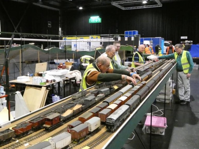
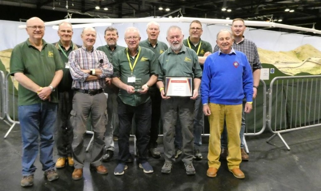
The highlight of February was the attendance of The Summit at Model Rail Scotland in Glasgow. The extreme logistics of this exercise, although complex, all went to plan. A few pictures follow, courtesy of Dave S who was one of the operators.

The layout was awarded 3rd prize amongst the “visiting layouts”;assumed to be those not owned by Scottish member clubs. First prize went to an N gauge layout with loads of moving vehicle and second prize to Peter Kirmond’s “This is York”, a 2mm finescale rendition of the inside of York Station in the 1930s.

A picture of the tightly packed van taken by Allan outside the CS2 – part Tetris, part Jenga!

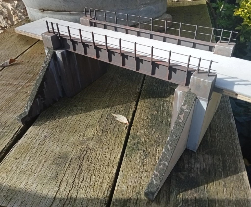
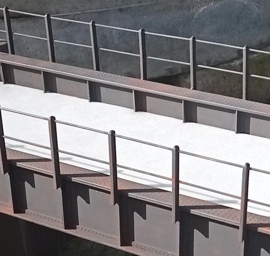
David’s new 7mm layout – Lyme Regis – is making excellent progress, and above are pictures of the girder bridge that Allan has made which carried the branch over the main line to the up side bay at Axminster. Lots of concrete of which the LSWR were something of a pioneer.

Those rivets (and the weathering) – lovely!

Peter’s EM conversion of the Rapido 15xx 0-6-0PT is virtually complete. The conversion has been a successfully completed after some more bushes had been made before an acceptable centred number were made (quite quickly with practice!). The issue of rotation in the wheel centre was cured by pinning the top hat section to the wheel centre.

Quartering proved a bit more difficult, basically by trial and error, aligning spokes etc. Initially the coupled wheels were fitted on the axles with just a small amount of roughing up the axle ends with a file. This technique didn’t work very well as the wheels wouldn’t run true. The wheel was resolved by making new axles and lightly scribing parallel lines along the axle with the lathe tool in the lathe. The driving axle was scribed where the gear fitted, and the gear was pressed on using the lathe, spacing washers were fitted and the wheels were pressed on a small distance and aligned by eye to the opposite wheel spokes and then pressed on fully. With the wheels and coupling rods refitted, a small amount of tweaking of the other wheels resulted in a smooth running chassis. In reality this took quite a lot of adjustment over a couple of weeks, before everything worked properly.

The valve gear was re-fitted and the eccentric crank soldered in place after Loctiting the crankpin in place. Markits plain crankpins were used, (threaded ones aren’t currently available). The retainers still have to be soldered onto the rear driven axle wheels. One of the Rapido rear wheel crank pins was damaged, and had to be replaced with the Markit’s crank pins – the threads are compatible with the Rapido wheels. Only the front wheels have retained the Rapido crankpins which have been recessed slightly into the wheel to clear the crosshead.

November & December 2024

First a reminder that The Summit is all set to be on show at Model Rail Scotland at the SEC, Glasgow over the weekend of Friday 21st to Sunday 23rd February (a three day show). This enormous 7mm Scale 0 Gauge scenic layout is based on the railway between Settle and Carlisle, requires a lorry and a large team to transport erect and operate it, and exhibiting The Summit is a major undertaking. It’s not unheard of for visiting locos to be given running rights, and our layout has been used at exhibitions to test locos before purchase. If you’re at the show please come along and say hello, and we’ll take it from there!

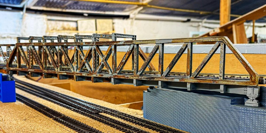
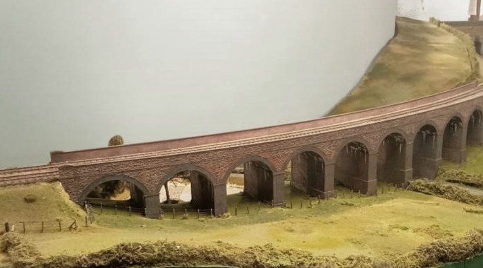
Over the past few months, Andrew has been working on the impressive flyover bridge for our 00 Gauge Heyno Junction club layout. The design was first created using CAD software, and the structure was divided into 12 sections for 3D filament printing. Once assembled, the bridge was painted grey, and Deluxe Materials’ Rust-It solution was used to give it a weathered, rusty appearance. To enhance its realism, further weathering is planned to make it look like it has stood the test of time. For the brick supports, he intends to clad the existing blocks with laser-cut plywood featuring a brick pattern, as the 3D CAD generated filament printed brickwork did not meet his expectations.

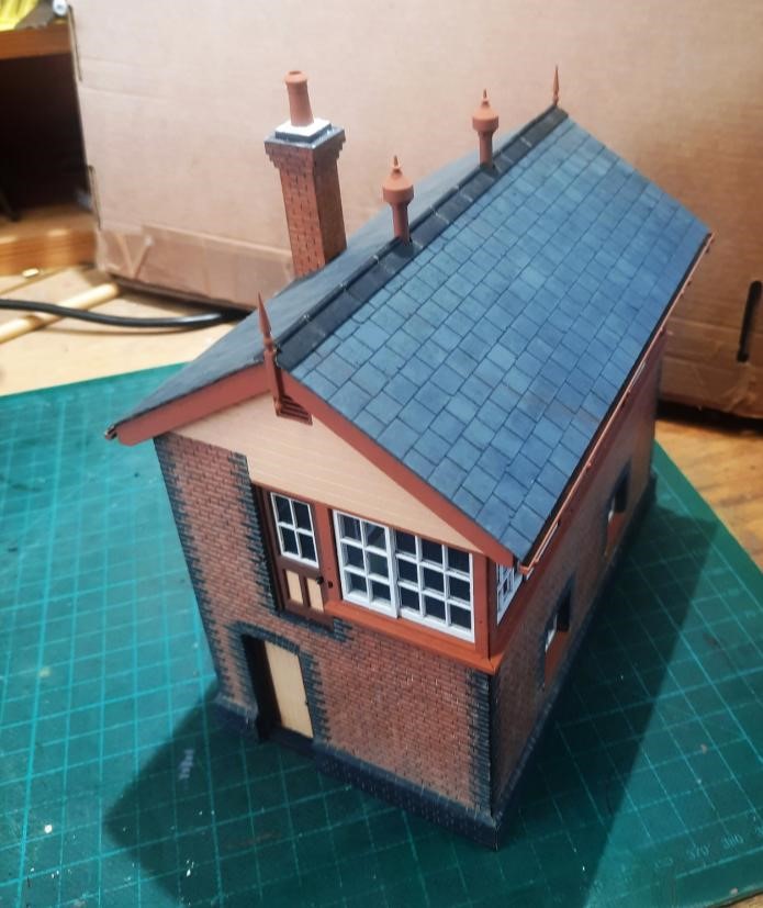
Allan has just finished this splendid 7mm model of the signal box at Cole in anticipation of his future layout of Cole station on the S&D which will replace Kingsferry in his railway shed.

It is constructed in card and Plastikard entirely from photographs as it was demolished when the line closed in 1966. It represents the signal box pre-nationalisation when the chimney was extant. It is finished in the brown and cream of the LMS parent company. Perhaps Allan was concerned that the Southern vivid green and cream would have shown up his collection of GWR engines in that dull browny-green so beloved of Swindon. A superb S&D model by an enthusiast for all things GWR – whatever next?!

2024 was a good year for 4mm scale Coombe Town as Dom managed to complete some major scenic projects including finishing the exterior of all the station buildings, adding the yard ground cover and building up the field in the front corner of the layout. All this has allowed him to start photographing some of the views he’s been aiming for the last five years, one of which is included here. 2025 will hopefully see the completion of major works with the road and Station Master’s house currently under construction, with the garden to follow to complete basic ground cover across the layout. Your editor reckons the overall look and that backscene are pure genius!

Simon K has completed the weathering of Alice for his 7mm scale NG Tynradd layout.

And Tynradd virtually complete – electrics to be finished and the buildings shown previously to be positioned in the far right corner. Anyone wondering about the name could just try reading it backwards…

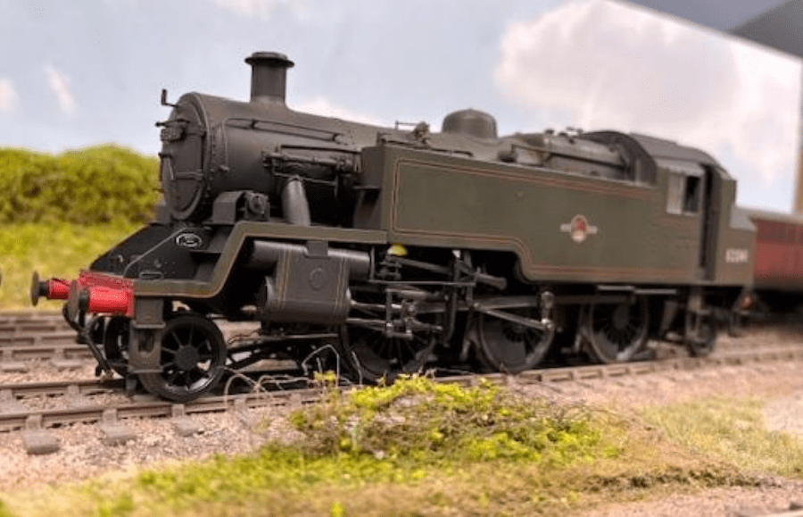
Also from Simon K, a picture of 82041 which was shedded at Bath GP so appropriate for S&D, but it and sister engines also ran on ex GW branches (such as that through Shepton) so OK for his little layout.

Dave H reports that City of Gloucester is coming along nicely – the picture shows the now running chassis. As designed the kit entombs the wheels and motor forever between the outside frames (a bit of a blind spot in an otherwise very good kit). He’s spent some time and bother making the outside frames detachable so that the wheels can come off for maintenance. It also needs special outside cranks made as the Slaters ones don’t work with GWR engines (the extended axles aren’t long enough). Luckily MOK supply some very good machined steel replacements originally developed for their Armstrong kit. The Slaters wheels are good – they screw onto threaded axles which is quite neat. The extended axles for the outside cranks have tiny squared ends to make sure the quartering is spot on.

Jim has been working away at constructing a train of 10 autoballaster wagons in 2mm Scale. They are N Gauge Society kits which will have 2mm finescale wheels installed at the last stage – not a straight-forward kit with a sheaf of very delicate etches. The first batch of five have brass etches but the second batch, yet to be started, have stainless steel etches so they may be a little more durable. Below is a picture of the prototype:

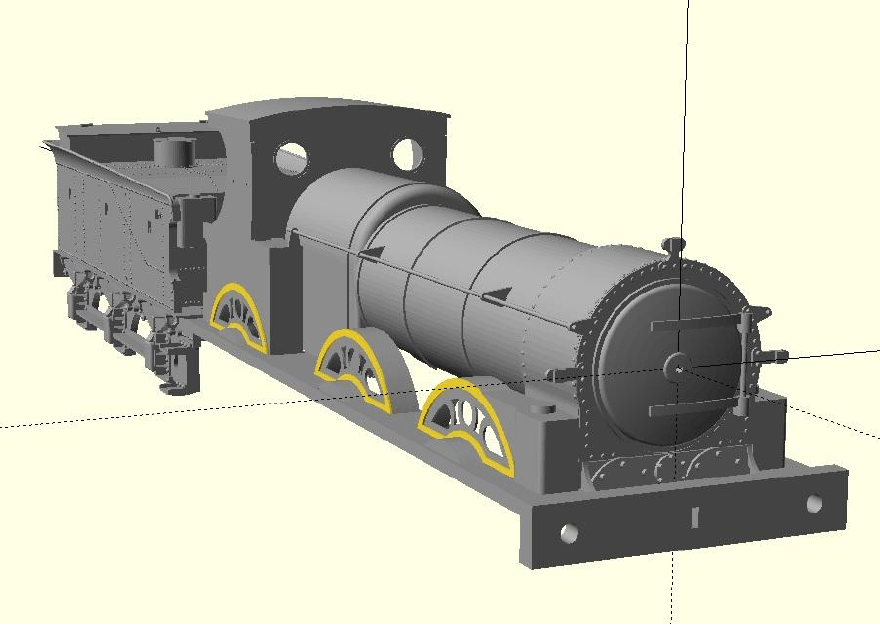
Missing so far from Steve’s putative recreation of the Downton Train Crash of 1884 is the Lion Class pilot engine Stour of 1869. So over the Christmas Holiday options were explored for modelling this Nine Elms built contemporary of the more well known Beyer Peacock built Double Framed Goods. This process turned out to be slippery slope. There were over forty examples of the class, and there are photos of a subset of these engines in Bradley, but none of Stour. The only drawing available was from the Locomotive Magazine from 1933 published in Mike Sharman’s collection of drawings. This is only a side view, but it was scanned, scaled and traced in QCAD and a start was made on developing plan, front and rear elevations from the very few known dimensions.

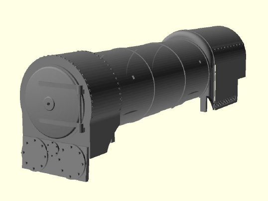
Slithering over the crest of that slippery slope, the boiler unit was modelled in OpenSCAD with a view to 3D printing it. The boiler then needed a backhead, and it needed to be a double firebox one as the Lion Class received the final development of them. The only drawing in Bradley was of 7′ 2-4-0 Clyde of similar vintage, but once traced it was found to fit inside the Lion Class cab like a glove. This is also the backhead that the crude example in the K’s kit was clearly supposed to represent so this will be an upgrade for Vesuvius Class 294.

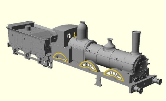
How to make the rest of this somewhat peculiar little loco though? Chemical Etching seemed the way forward for cab, splashers, running plate etc., so the sorts of etched shapes needed were mocked up and a start made on assembling them around the boiler and smokebox unit. This allowed Steve to pose his 3D model against photographs allowing adjustment of the jigsaw puzzle of etched parts to improve the proportions, and confirm fit of the different components. There was now the boiler unit (and backhead), sitting on a reasonable looking running plate with the filigreed splashers and fitted with an Adams’ cab. To robustly model the ‘face’ a half etched smokebox surround was drawn up to also represent the handrail brackets and lamp irons, with the fastenings for those to be pushed through from the back. The smokebox door and hinges, will be 3D printed as will the sandboxes and buffer beam. There’s a gap behind the huge wooden buffer beam on the prototype for access to the cylinder covers, and the cylinder block is clearly angled to align with the crank axle.

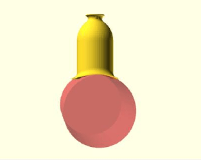
Adams’ stove pipe chimneys are available commercially so not a problem to obtain, but Steve is not aware of any source for those distinctive Beattie domes. As has been mentioned earlier in the thread, OpenSCAD has no tools to flare one cylinder into another, but conceptually rolling a ball round the junction of the two cylinders must just be a matter of some convoluted trigonometry. This needed to be a generic capability so the boiler and dome size and the required flare were all parameterised. Segments of flare were hung round the dome and the correct height of each segment calculated using somewhat rusty trigonometry so that the corner sat at the junction of the two cylinders as shown above. As can be seen this didn’t completely reproduce the ‘ball rolling round the junction’ effect that was required.

Having an engineering background rather than being a mathematician Steve resorted to a more empirical approach to resolve this problem by adding a ‘fudge factor’ (in this case 1.55) for the vertical axis that can be adjusted to further drop the curve of the flare in the correct position for the two cylinders. This left a bit sticking out each side of the ‘saddle’ and this was removed by an intersection operation with an elipse of a ratio of a second fudge factor (in this case 0.95). No doubt a mathematician could come up with a suitable formula for these two crucial values, but that’s something for another day. For Stour and 294 these domes would have been painted, so they will be printed in positon on the boiler, though hollowed out for resin drainage and for weight to be added.

This is the loco attached to the tender. The dragbeam (and running plate) is currently a scale 6’6″ wide and that seems very narrow. The running plate is visibly 6″ narrower than the bufferbeam, that in itself is about the same width as the Beattie tender buffer beam. Photographs confirm that the loco was narrower than its tender but by this much? The Stour of 1884 would have had a sort of pressed steel looking Beattie cab, and the CAD for that will be more cardboard based to try to confirm what an etch for that should look like.

Steve likens his approach to scratchbuilding in CAD rather than commercial kit development allowing a less rigorous approach to be taken to the design. His model will be 4mm scale EM Gauge, but a couple of friends might build ones in 00 and P4 Gauges. The use of 0.4mm sheet for 4mm scale etches might enable models in S or 7mm scales using proportionately thicker etched material with the 3D printed parts scaled up, but his own model of Stour in 4mm scale remains the main objective.