A short month, but still plenty going on. Our big news, and a huge relief to members, is that our long running Business Rates problem has finally been resolved. A successful appeal with professional help to the Valuation Office has taken the Rateable Value of CS2 to below the 100% small business rates relief threshold, and as a result our very large back-dated business rates bill has been reduced to zero!
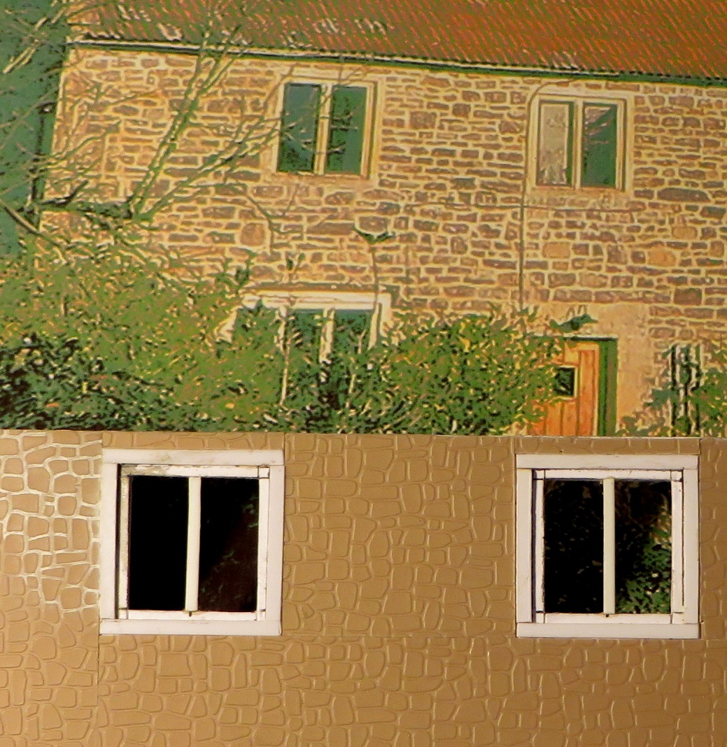

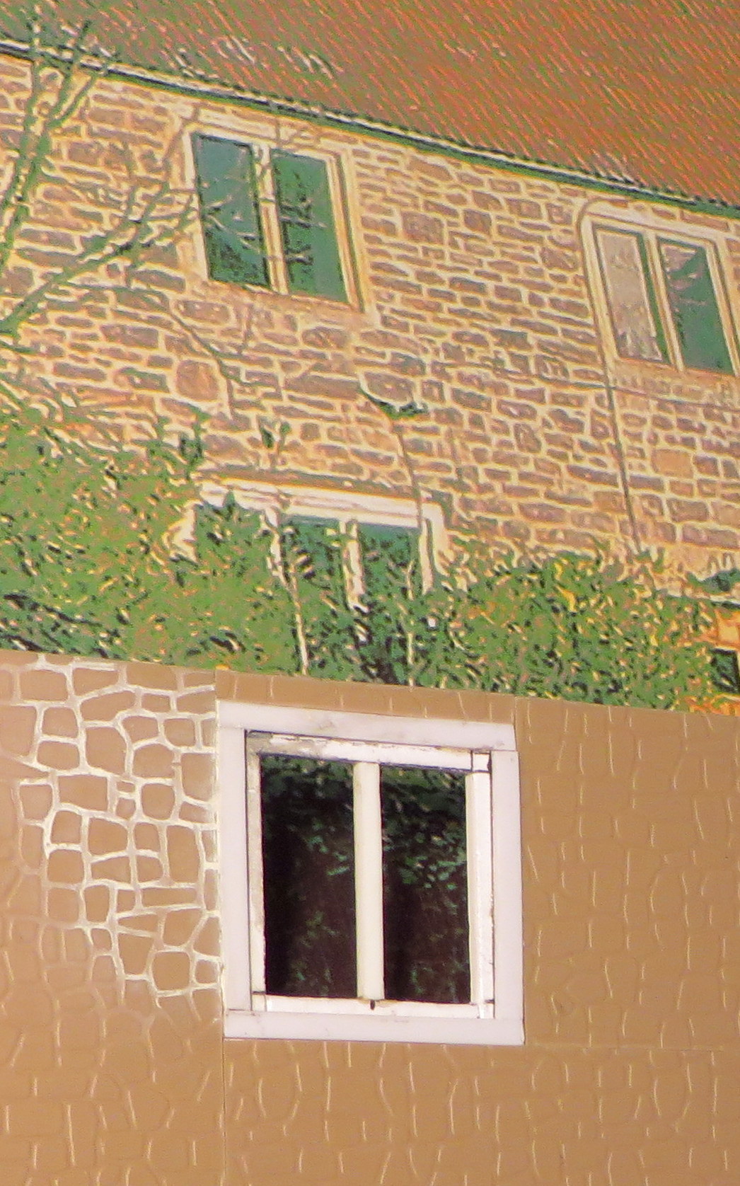
For Evercreech New a start has been made on the farmhouse that will live behind Prestleigh Viaduct. The photos show the front elevation – yes, the nice view no one but the operators will see! It has a card carcass faced with Slaters random stone sheet. Plastikard is used for the stone window and door surrounds which are flush with the random stone which has been cut around them, with stone mullions in a thicker Plastikard let in. The casements with central glazing bar might be in soldered brass, glazed of course, set behind the card carcass. A small area of white mortar has been added which picks out the stones nicely. The random stones aren’t quite a match with the original but in our view close enough.
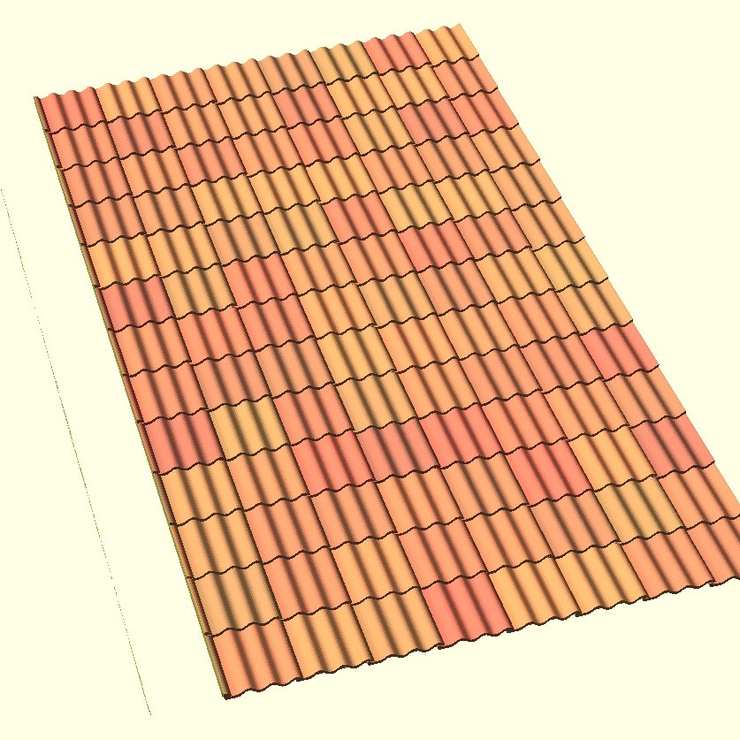
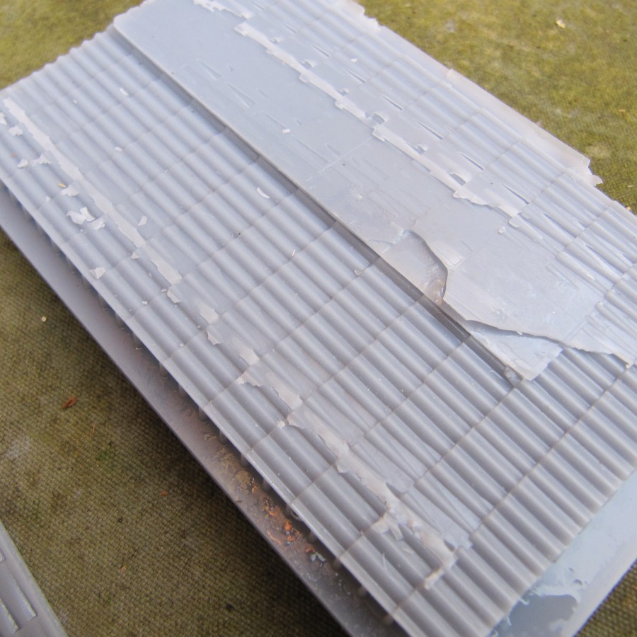


The Triple Roman tiles employed on the farmhouse appear to be unique to Somerset and are not available commercially in any scale. An attempt was made to 3D model a small sheet of these tiles from an original tile. A small element of randomness was introduced to tile height and lap of each tile to improve appearance. The only successful print (of many attempts) was at 25° to the build plate giving a massive 12 hour print time. This print might have been the basis for a mould to resin cast the rest, but the plan now is for the roof to be made from Slaters corrugated sheet cut into horizontal strips overlaying each other and scribed down the roof slope to define the individual tiles. This produces a very good replica of this pattern tile. Painting should be fun – in a way that only a true artist could appreciate!
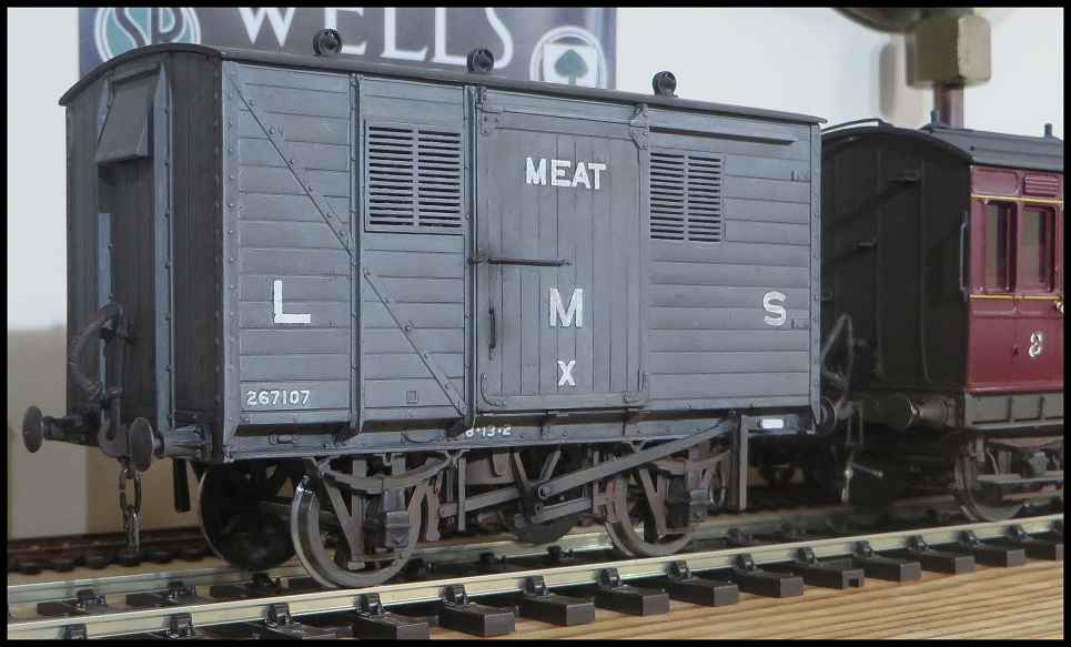

The now completed Parkside LMS meat van. In what will prove to be a disappointing blog for the rivet counters out there, purists may query the under scale lettering, Allan being too mean to buy one sheet of 0 gauge HMRS Pressfix transfers for just one model (actually two – there’s the other LMS box van previously published on this site). He used the largest lettering that he could find from a 00 sheet as the transfers included in the kit don’t work for him. There are no heating pipes fitted – the assumption being that these vehicles were attached to express fitted freight trains not passenger trains.


Out of the blue as far as this blog is concerned is this very nice Claud Hamilton D16/3 in 7mm has been leaded and now weighs enough to balance nicely on the driving wheels which are beam compensated. Not shown are the boiler backhead which is solid lead and awaits detailing and the underside of the cab roof.

The Clauds had splashers for the bogie wheels which were quite decorative and the locos retained these on rebuilding. None of the etchings acquired over the years had parts to build them, so these are made out of three pieces of brass and the photo shows where they will be located. A club e-mail exchange has established that these parts are being assembled on a well used example of the very finest sort of ceramic soldering mat! We would definitely like to see a lot more of this engine!

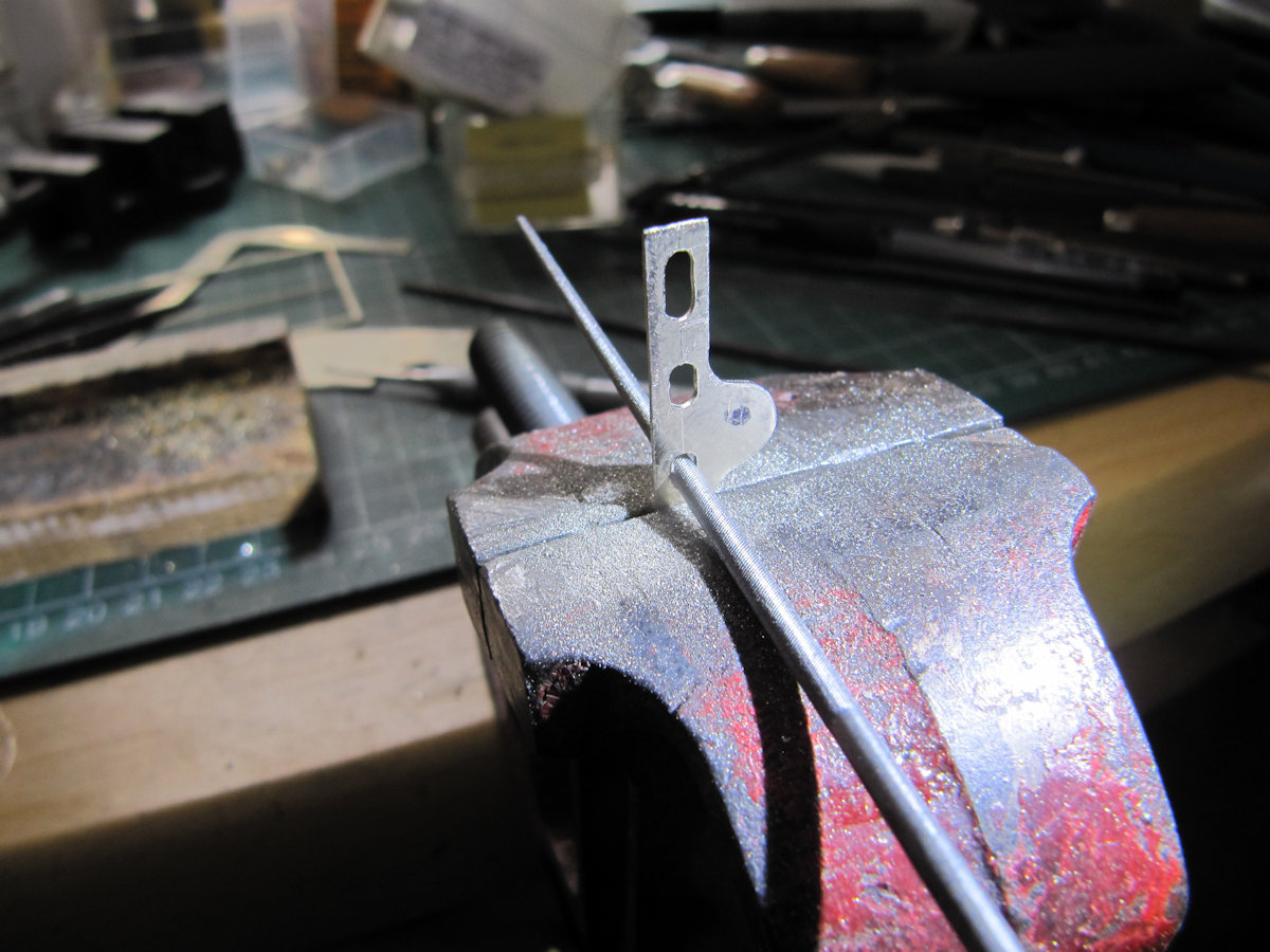
Peter discovered a couple of Cambrian Kits in his stockpile, the 25T one will be built as a WD one like the one at Yeovil Junction. The kits aren’t the best but with a bit of work and replacement parts they come out OK. A bit like the early Ian Kirk kits, which became Parkside and are now Peco. The tooling was all hand sunk just like Airfix. With the ‘benefit’ of being able to work on the real thing, the supplied brake shoes were obviously the wrong shape, so photos of the real thing were traced and a 3D model produced with a view to getting some 3D printed.


For Verwood the month produced a complete painted ground frame hut – though not much else! There wasn’t much of a plan when started, other than to attempt a modelled interior. The same corrugated sheet that was used for the lamp hut was employed, but this was laminated in two layers using epoxy resin to make it stiff enough without risk of solvent warping. The internal framing is purely decorative and applied with solvent. Rivet counters should look away now, for in counting the corrugations (as you do) I came to the conclusion that there were four corrugations where there should be five, something not noticed on the lamp hut. In addition, the timber framing is a square section and that’s unlikely too! As this is for an EM Gauge layout, I shall fall back on this being only an artistic impression. All photographs show the ledged and braced door to have been left open when the station was manned. This may allow a glimpse of the four lever knee frame, one that may have to be 3D modelled and printed from an example now at Midsomer Norton station when the law finally permits a visit. The only colour picture shows that the exterior had faded to a sort of gungy grass green. This same photo seems to show that the roof was the same green, when the Southern painting spec says it should be grey. I’ve assumed that the door was closer to a normal Southern mid-chrome green
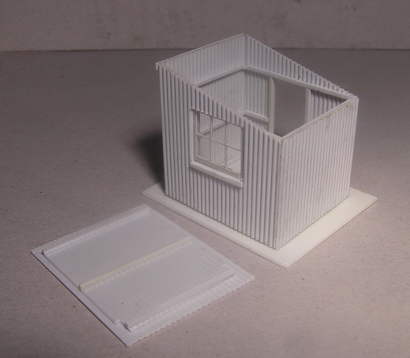

It is most unlikely that the interior was ever lined or painted so is light grey to represent galvanised zinc ,and the framing is bare wood. The window is far too fresh looking and needs weathering. No laser cutting or etching for this one – it was all done the old-fashioned way. Of the three corrugated iron huts at Verwood that were in the immediate station environs and therefore should have been painted green – the lamp hut was black (ish), the ground frame green (ish), and the only colour photo showing the weighbridge hut (in next month’s update if your editor is spared) appears to show it to have been pale blue. This last is now thought to be a colour cast in the Instamatic photo, and it is actually just grey (ish) with a white window- but what colour to paint the door? It does seem to be a darker shade as does the roof.
The smooth rolling chassis of DaveS’s 7mm Black 5 is the featured image this month and what follows is a truly epic update on how this came about in our hero’s very own words:

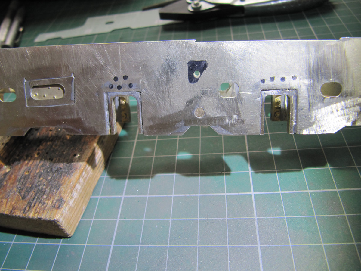
Best start with the frame modifications. Small filler pieces were cut from the etch that the frames came from – correct thickness. These were soldered in place and filed to shape. The extra holes in the frames were also removed apart from the black triangle in the second picture. I decided not to cut that out as I’d have to make up extra supports for the Weigh Shaft that uses the small hole.

Once that was done the slide bars and their support casting were attached. The slide bars had already been fettled to ensure that the crosshead slid nicely in them. The support casting was modified to accept the slide bars. I did not attach the slide bars to the support casting, I did not see the need. Assembling the connecting rod, crosshead and centre drivers we find that it all works well with no binding.
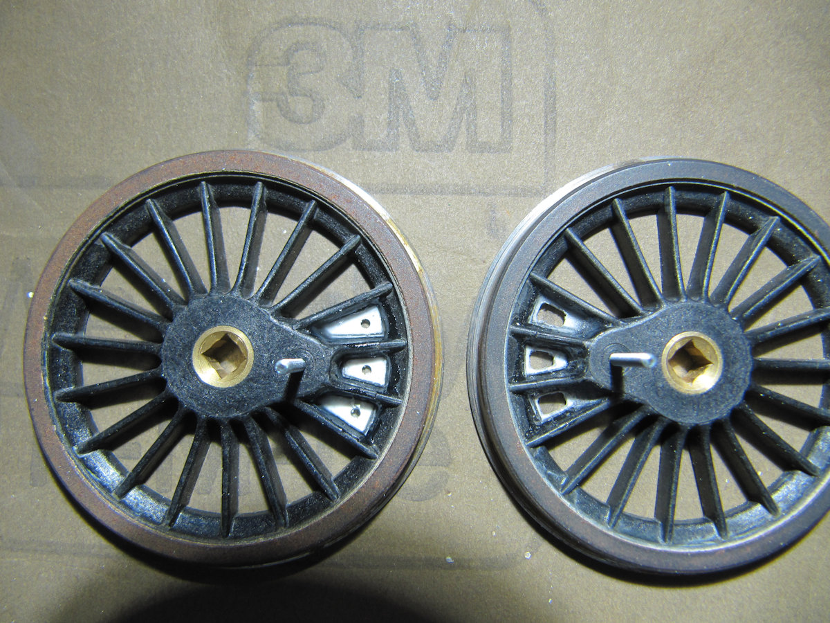
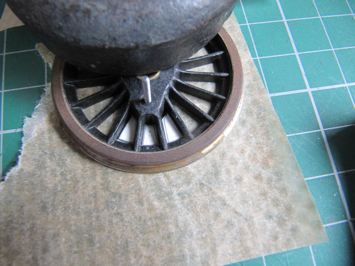

The centre driving wheels (on my prototype) have stiffening webs round the crank pins. This detail was added to the wheels along with the balance weight etchings. Note to self, do not use the thick end of a cocktail stick to paint with – a brush may give better results.
Looking ahead one wonders about the best way to attach the return crank to the crank pin. Reminded by Keith, I looked at Bob Alderman’s instructions when he did his 8F. “Solder a Tapped Top Hat Bearing (TTHB) to the inside of the return crank”. This is all very well if you have TTHBs to hand. Here’s how I made mine.
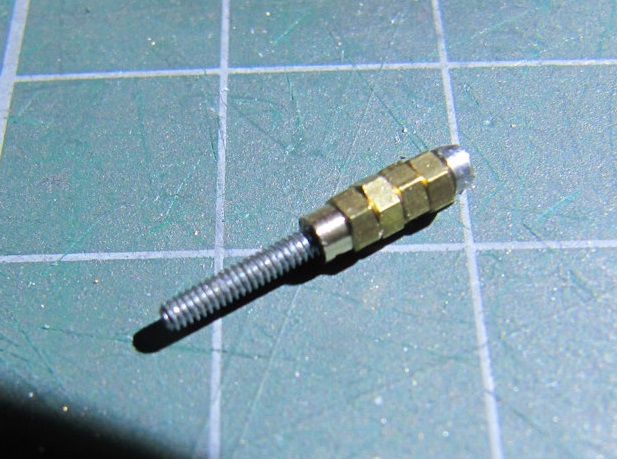

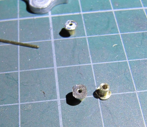

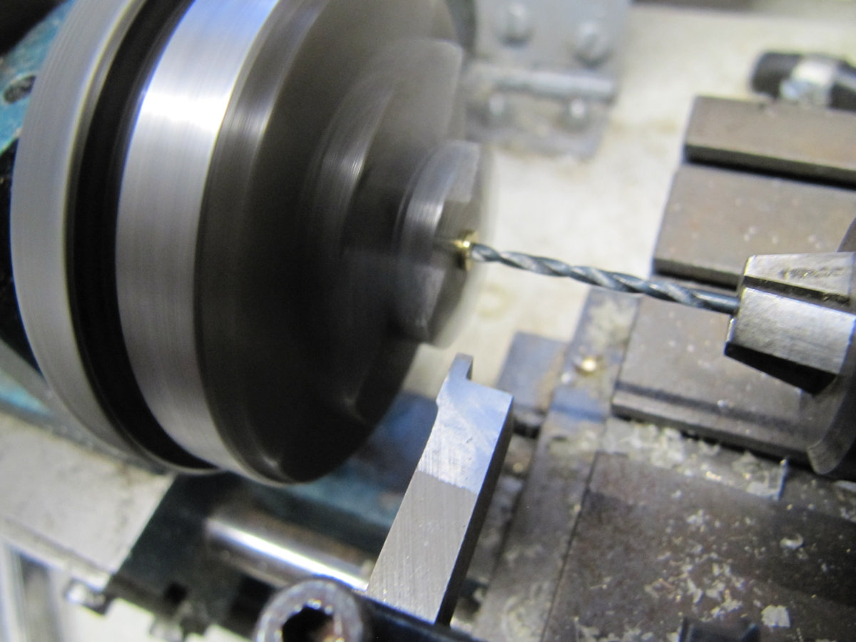
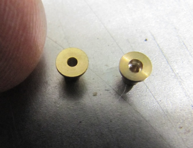
Take six 12BA nuts (you’ve got 6 cranks to do) and assemble them on a long 12BA screw. Put the assembled nuts and screw in a small drill, the threaded end being held in the chuck. While the drill is revolving, use a file to take the corners off the nuts until they are round and about the size of the screw head. Measure the diameter of the filed nuts so that you can stop when you get to the size of available drill – I used 2.1mm. Next put a Top Hat Bearing (THB) in your lathe. Drill into the THB to a depth not greater than a modified nut. Other methods of doing this are available. Put a modified nut into the hole in the THB. They were a tight fit and needed to coaxed in with a hammer. Check that a 12BA screw goes nicely through the assembly. Add a small bit of solder round the nut. I had an oiled 12BA screw in place so that solder did not go down the thread. A quick filing finished off the assembly.

I used a mixture of pins and 14BA screws to assemble the valve gear. Not too many pictures were taken here. One side was a learning curve and some of the rods had to be shortened due to replacement casting being used which were slightly larger than the supplied white metal ones. The right hand side valve gear was eventually assembled and worked well, again, without binding and without the coupling rods. The thinking was that if they work individually then they’d be ok when assembled. And yes they did, but that surprise came later.

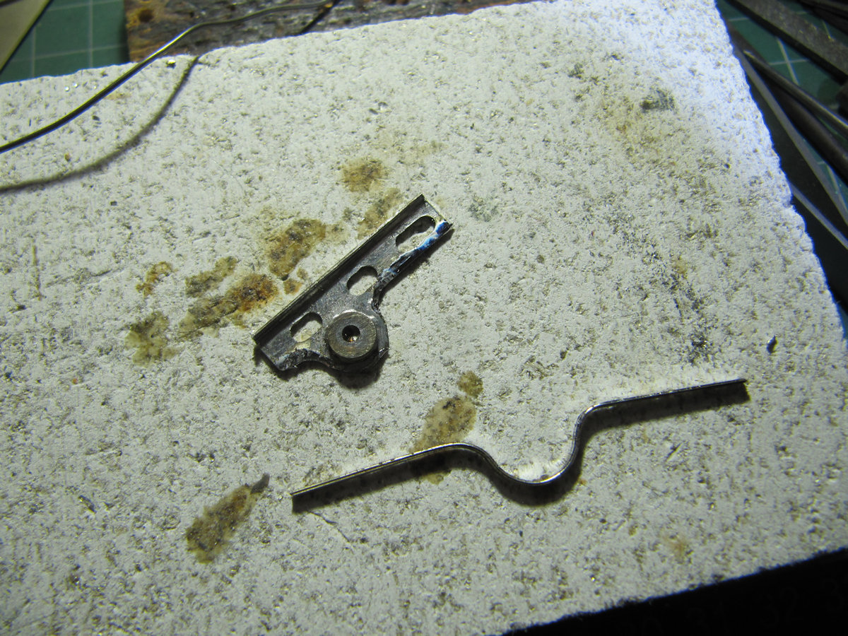
The expansion link trunnion castings needed modification on the inside to allow the link to rock. This trunnion casting was the one that was missing from the kit and supplied by Dave H from Bob A’s box of white metal castings. On modifying the casting for the left hand side, brain fade struck – I modified the wrong side! Could I make a recovery? In a word – no, so a fabricated one was made up from nickel silver sheet.

Once that was completed the final assembly of all the valve gear, con rods and coupling rods was done on both sides.
[Ed] – a video with a most unexpected soundtrack has been circulated to members that proves the complete assembly to not only look good, but to be very free rolling!
With widespread vaccination and an end to lockdown finally mapped out, we can possibly look forward to a return to CS2 after 17th May 2021 – applying any government guidelines that would be necessary for such gatherings. A trustee meeting this coming Wednesday may discuss a way forward to the re-opening of CS2.
