

It turns out that yard cranes on the LSWR were a very diverse bunch indeed with no typical LSWR type as such. Certainly the two cranes at Wimborne were of different designs, that both differed from that at Verwood. A very grainy picture of the one at Tisbury shows it to be similar to the Verwood type and it is likely that the crane at Semley was also of the Tisbury and therefore Verwood type. As yard cranes go Verwood was quite well photographed although always incidentally. The photographs show a marked similarity to a very clear photograph of the yard crane at Crawley, and it is from this crane that the basic proportions and layout have been taken although both safety guards and jib were of a completely different design. Another source for details has been the ex-LNWR crane at Conway.
The crane was at the back of the yard in front of the Dorset Farmers depot. It was mounted on a bank retained by a sleeper built wall which gave it additional lift. It is known that it was regularly used to load both logs and containers of finished furniture. All photographs show the crane neatly tethered. Since this loading bank was used as a vantage point for conventional railway photography (containing locomotives) parts of it do appear in extreme close-up!
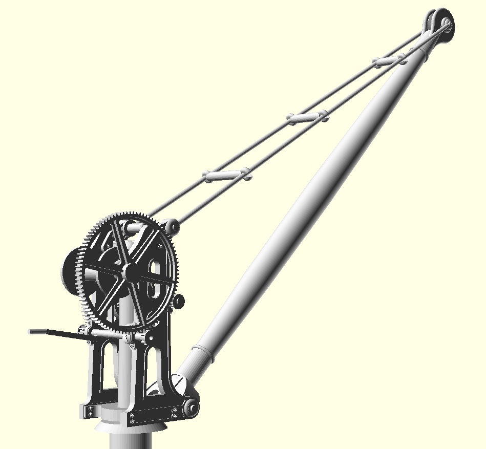
We have three dimensions for the Verwood crane. The lift is recorded as 23’6″ in the SWC Portfolio which would include the bank estimated from photos to be 8′ high. The reach indicated on the 40′ plan is 16′ 6″, and a typical height for the crank axle on similar cranes is 3′. Using these dimensions the jib ends up at 45° and stay wires at 60° to vertical which feels like sound engineering.

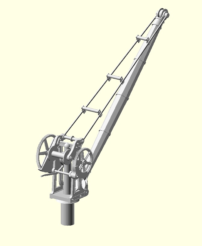
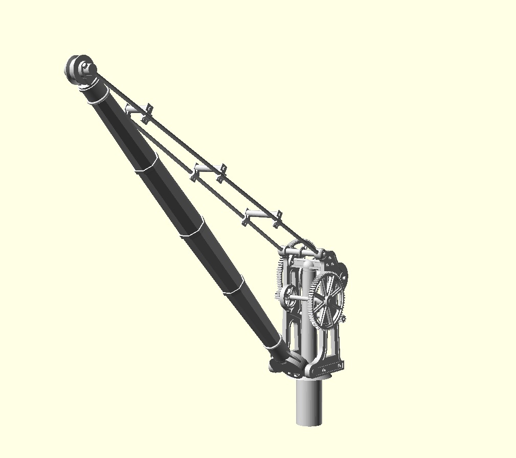
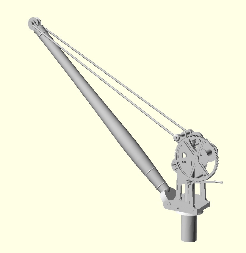
The model crane has been drawn up as a series of 2D drawings in QCAD which have been extruded and then assembled in OpenSCAD an approach which worked extremely well enabling me to produce the initial 3D model within a week of downloading OpenSCAD. At this stage a test 3D print was ordered, and it was the crane assembled from this test print that was shown at the South Western Circle meeting at West Byfleet in October 2019, and that can be seen in the feature on Semley in the January 2021 edition of Model Rail. Once viewed in position on Semley the 3D CAD was significantly reworked to improve the scale and proportions. In particular the jib has been significantly beefed up, the size of the frame reduced to set the crank height at 3′, and the stance of the crane improved by widening the frames slightly.
The model is produced using stereolithography in a resin bath. The resin printed parts are as follows:
- Frame
- Pillar
- Pulley End of Jib
- Frame End of Jib
- Small and Large Gear wheels
- A set of Three Rollers
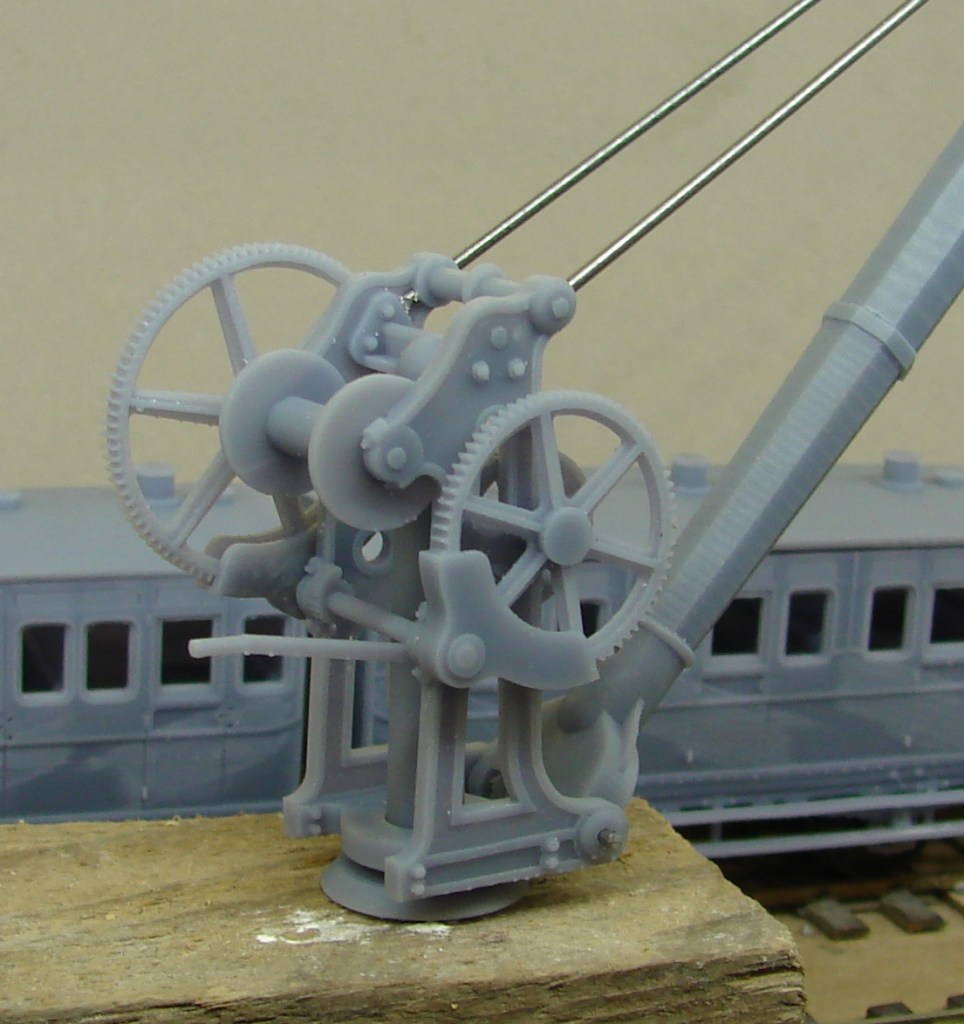
The test build showed that even in warm weather the resin was prone to wilt and that the pillar and jib would need to be reinforced with brass tube to stabilise it. The 3D model was therefore amended so that a central hole is printed into the pillar and the two jib halves ready to receive this.
The frame simply sits on the pillar, and the assembled jib is fitted to the body using a single 0.9mm pin that passes through the jib base wheel, representing two of the spokes in the process. Holes have been provided in the body and pulley end of the jib to take the 0.7mm stay wires one of which will need to continue around the front of the pulley to form the stay to stop the chain from unshipping. The chain is metal but the rollers are 3D printed and slide into place between the stays. There are holes at each end of the winding axle to take either a spike or a handle depending on which side it is being wound from.


And the test build of the 7mm crane about to be dismantled and sent on to its new owner. The revised 4mm kit has been delivered to Semley and another has been sent to Canada.

‘Swanage’ Yard Crane
A couple of these cranes have been sold for models of Swanage, despite the Swanage yard crane not being well photographed and probably removed before WW2. Despite a lack of clear photographs we know that the Swanage Crane whilst not dissimilar in outline to the Verwood/Semley crane, differed in two important respects; the gear wheels had eight spokes and the big gear wheel was on the opposite side.
Through the power of CAD and 3D printing I was able to generate the frame handed and draw up the necessary eight spoke gears. We don’t know too much about the prototype, so this cannot claim to be an accurate model of Swanage, but this version of the Verwood/Semley Crane does I hope give a reasonable impression of it.


‘Wimborne’ Yard Crane
There has also been interest in a ‘Wimborne’ model that is a handed version of the Verwood crane and represents the crane found on the up side at Wimborne which was opposite hand to Verwood and also had guards fitted.

‘Belturbet’ Yard Cranes
For modellers of Northern Ireland Railways a rounded boom can be supplied based on that at Belturbet.
‘Brighton’ Yard Cranes
A member of the Brighton Circle sent me photographs of three yard cranes all on LBSCR territory. All have frames that look identical to Crawley (perhaps no surprise there) and Verwood. A not unreasonable conclusion is that they had the same origin. In each case though a different pattern of boom was fitted, with round, octagonal and square designs featured. Despite this all the Brighton examples seemed to have the same distinctive pulley and wheel metalwork that was quite different to that at Verwood.
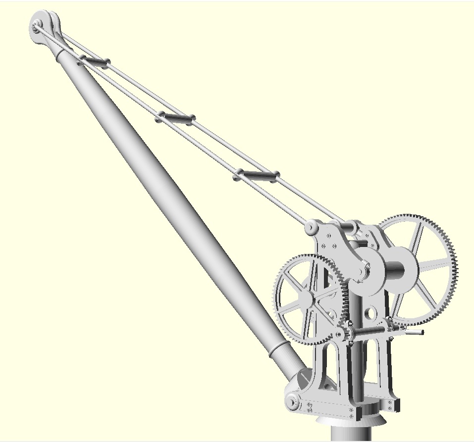
A photograph of one of the frames was particularly useful in showing parts of it never seen before. Using these views previously missing detail has been added to the Verwood and Semley Crane models. For all versions the base was extensively revised, the brake wheel has been enlarged, brake and ratchet have swapped sides, the bearings have gained end caps with bolts and the tiny cogs have all gained end plates too. Reserved for the Brighton Yard Crane are the low profile rollers and rounded jib/boom.
Availabilty
Kits are available in 4mm and 7mm scales, and the following models are available:
‘Verwood’ – Original Crane with six spoke gear wheels and safety guards.
‘Semley’ – a Verwood crane without the safety guards and suitable for earlier periods.
‘Swanage’ – a handed version of the Semley crane with eight spoke gear wheels.
‘Wimborne’ – a handed verion of the Verwood crane, thus with safety guards.
‘Belturbet’ – generally a ‘Semley’ Crane with Round boom and no rollers.
‘Brighton’ – generally a ‘Semley’ Crane with Brighton round boom and low profile rollers.
Although some versions of the kits may be in stock, any version can now be printed on demand on my Anycubic Photon Mono 4K printer in Anycubic’s Water Washable ABS-Like Resin 3.0.
All enquiries to: verwood.crane@gmail.com
