The mechanical and electrical parts have been successfully completed of the D16/3 and fine detailing can now commence. Part 1 is here.

I will begin with both ends of the boiler. I have turned a smokebox end from two pieces of eighth brass soldered and riveted together so that it looks like the wrapper is fastened to a pressing. The smokebox front provided in the kit was a stamping complete with rough edges.
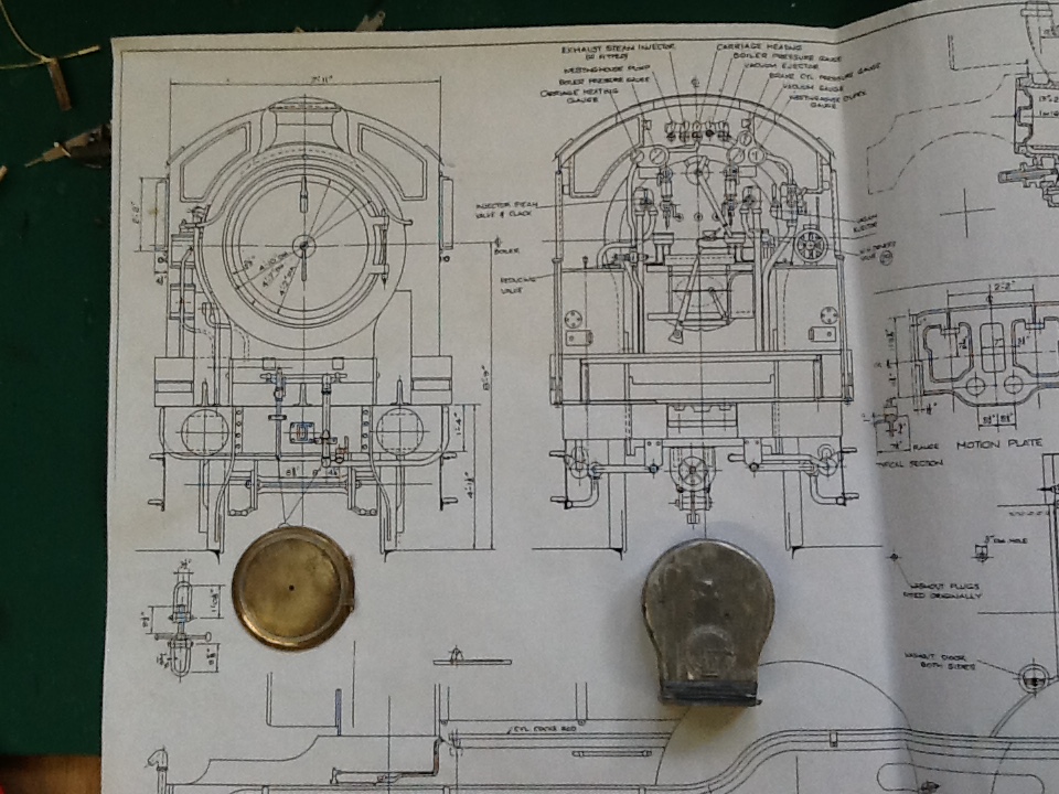
Modelling the steam fountain for the D16/3 which is fastened to the top of the firebox and distributes steam to various controls. From left to right are steam to the Westinghouse brake pump, the exhaust injector, the carriage heating, the boiler pressure gauge and the vacuum ejector. On the real thing the isolating valve handles were brass but I only had nickel silver ones. The brass casting came from Ragstone Models.
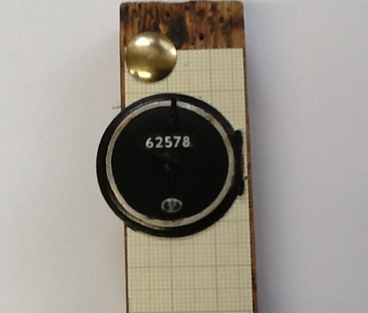
The D16/3’s smokebox door is finished and ready for eventual fixing. I had the whitemetal one that came with the Mallard kit. The master had obviously been lathe turned because the tool marks were still visible. Useless, so it will form part of the ballast in Simon’s ex WR toad. The other I picked up at some show and is a brass casting. Because I wanted the loco to have the attractive steel ring featured and don’t like metallic paint I lightly tinned it. The number and shed plates are from Guilplates If like me one has difficulty painting the white numbers , here is a useful dodge. Pick them out in white gloss paint being careful not to fill the voids of the noughts and sixes too deeply. Allow a couple of days for this paint to harden and then paint the whole plate black and while still wet drag the plate face down on a piece of paper which has to be on a hard surface. It works every time.
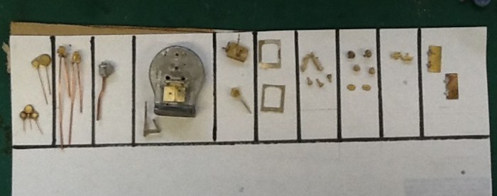
Most of the backhead details are now ready for painting and installing on the firebox back. From left to right they are:-
- Pressure gauge clusters. The top two go on the firemans side, the small one Is for the carriage heating and the large one the boiler pressure. The cluster of three go on the drivers side. The top one is the brake air pressure, the left lower shows the rate of vacuum and the right lower the state of the Westinghouse duplex gauge. No etchings for the mounting of these were included in any of the frets I have , so they were filed up from bits if scrap.
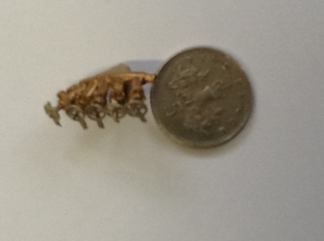
- These are the clack valves from the injectors to fill the boiler. The castings came from Laurie Griffin.
- This white metal casting represents the all important brake valve. It is not quite correct as it should have two operating handles, one for the air brakes and another for the vacuum brakes. I have no idea where this casting came from.
- The backhead with the fire doors and the open and closing levers ready for installing once painted. The fire doors are from scrap and the levers are a casting from Ragstone Models.
- The regulator boiler gland and lever. Castings from Ragstone as is the reversing wheel and leaver. On the real thing this is a complicated piece of kit. The reverser was air operated and in normal service was operated by the wheel. The lever allowed the driver to override this function. It does not go on the backhead but is mounted on the top of the splasher. I have somewhere a full description of how this worked but can’t find it.
- The etches I accumulated did not contain the movable cab windows so I filed some up from brass. They were made of wood on the real thing. The RCTS Green Guide says the front ones were fixed glass and the moveable ones were lowered like a carriage window by a strap. Where this lowered window went I have no idea because the distance between the bottom of the frame and the top of the splashers was too short. Despite what the Green Guide says some locos had sliding frames. I have photos of both.
- Two boiler water gauges and three washout plugs. Castings from Ragstone.
- Various hand wheels hand hole covers.
- Two lubricator boxes which are installed each side of the cab to feed oil to the rear axil boxes and horn guides. Castings from Laurie Griffin.
- Cab doors. I have yet to see a photo of them closed!
When all this lot is finished it will be put on one side because there are a lot more cab details to add. Not least the roof!

The front of the loco is now finished. The bits on the crowded buffer beam from left to right represent Great Eastern pattern standard buffer, guard iron, Westinghouse brake hose, coupling hook, vacuum brake hose, carriage heating hose and L H buffer. The lamp irons will be straitened just before painting and the buffer heads will be added after painting.
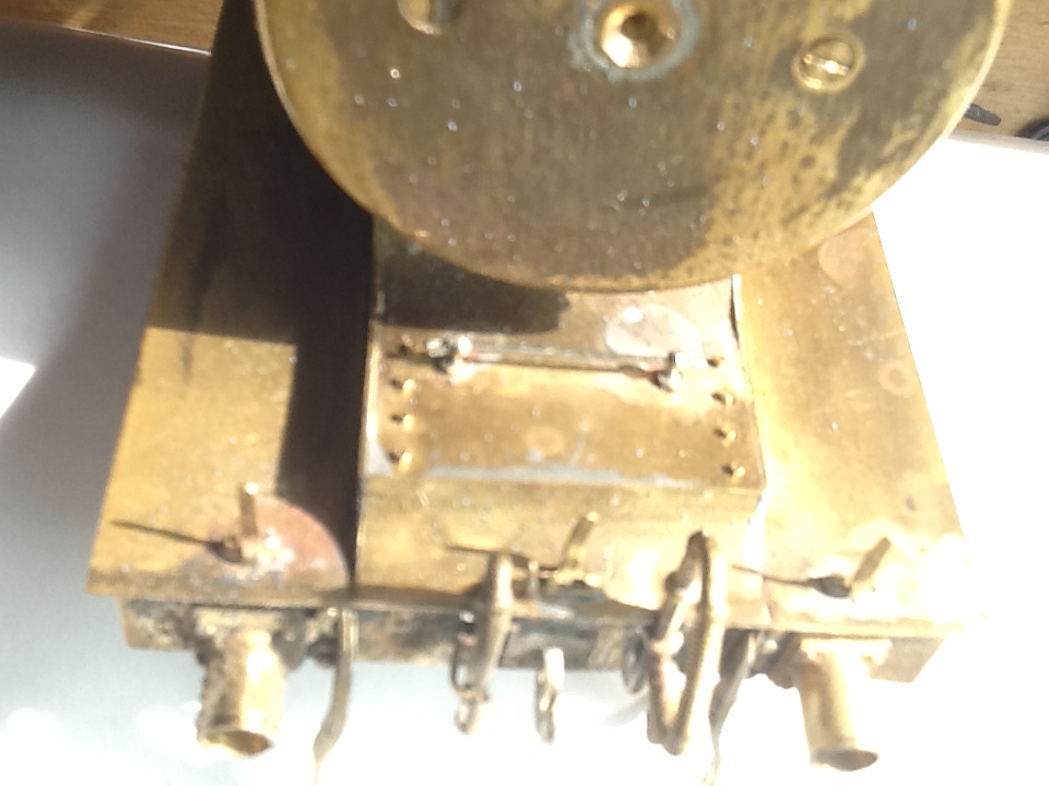
The right photo shows the various details of the removable panel used to inspect the cylinder heads. On the real thing it was held down with hexagon bolts. When we were in Leipzig with Gas Works I bought some dummy bolts from one of their trade stands which measure 0.8mm across flats. I don’t know why I bothered really because I can’t tell they are hexagonal at normal viewing distance!
Now to go amidships. The right hand side of the loco has about ten times as much detail as the left.
To be continued…
